Power Drill Alignment and Depth Measurement Device

a technology of depth measurement and power drill, which is applied in the direction of portable power tools, manufacturing tools, transportation and packaging, etc., can solve the problems of cumbersome carrying depth stops for each drill bit size, difficulty in inability to achieve physical or visual alignment, etc., to achieve efficient and economical means of alignment

Inactive Publication Date: 2015-06-18
HOLLAND JAMES
View PDF9 Cites 33 Cited by
  • Summary
  • Abstract
  • Description
  • Claims
  • Application Information

AI Technical Summary

Benefits of technology

[0020]The invention provides an efficient and economical means for alignment of drill bits on a variety of surfaces, including flat and curved surface

Problems solved by technology

Other challenges include a surface that is not static in its alignment, such as on a boat, in difficult locations such as small, remote, or hard to reach areas (e.g. inverted or overhead areas) that do not allow a physical or visual alignment of the hole to be drilled, the drill, and the operator.
The depth at a hole is to be drilled presents a challenge as well as the operator outside the machine or tool shop does not have access to a drill press that has drill stops built in.
The alternative of carrying depth stops for each drill bit size is cumbersome and the stops themselves can damage or deface the material surface and/or the drill bit itself.
The result of a misaligned drilled hole or a hole drilled to the wrong depth can be exceptionally expensive on installed items and structures on which drilling a hole is performed in both time and material.
While these devices and methods are feasible, the lack of wide or commercial adoption is indicative of their sub-optimal design.
Most of the current devices are unable to be used in difficult locations, such as small areas, remote or hard to reach areas that do not allow a physical or visual alignment of the hole to be drilled, require ancillary equipment, provide alignment only on a single plane, and/or are expensive.
Optical solutions to date typically do not provide sufficient feed back to the human eye to ensure alignment.
Furthermore, some optical devices do not t

Method used


Image

  • Power Drill Alignment and Depth Measurement Device
  • Power Drill Alignment and Depth Measurement Device
  • Power Drill Alignment and Depth Measurement Device

Examples


second embodiment

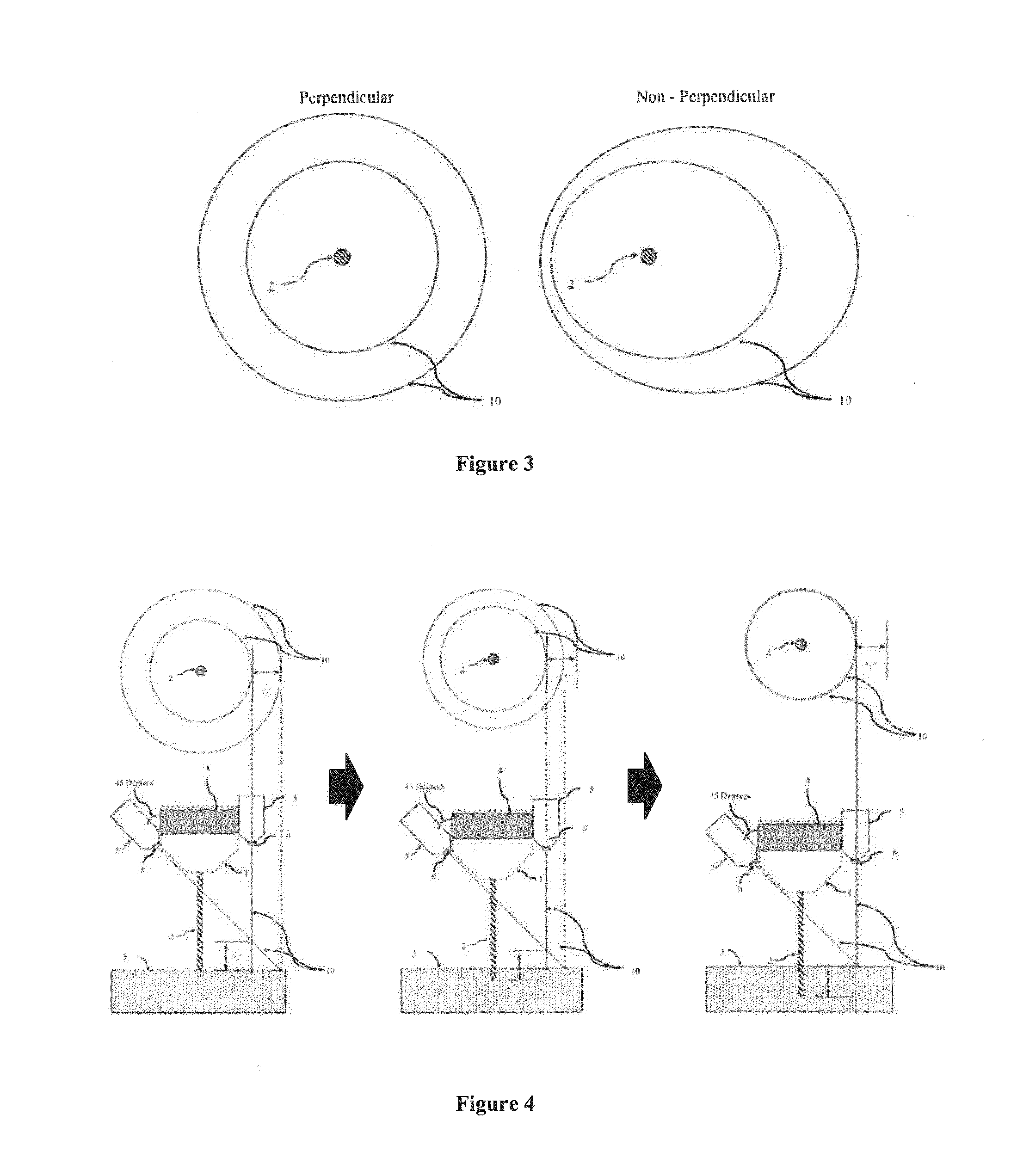
[0082]the invention with fixed angles of the lasers, non-perpendicular to the work surface, that creates concentric circles near the drill bit, is shown in FIG. 5. The preferred angles for the lasers in this embodiment are one fixed angle (e.g., 15 degrees) and one 45 degree angle measured off the line parallel to the drill bit longitudinal axis. Other angles are also acceptable. This design eliminates the need for the operator to adjust the angle of incidence of the lasers for simpler operation.

third embodiment

[0083]FIG. 6 shows the invention utilizing a single laser, set a 0 degrees measured off the line parallel to the drill bit longitudinal axis used in conjunction with the track template as shown in FIG. 7. The light trace is at fixed diameter parallel to the drill bit longitudinal axis and equal to the trace template, which acts as a target for the rotating beam. A perpendicular alignment will result in a steady illumination of the light on the reflective track and resultant dark spots if the drill bit alignment is not a perpendicular.

[0084]FIG. 8 demonstrates the use of a translucent plane to assist operators in utilizing the invention on work surfaces that are very small, narrow or have a complex topography.

[0085]FIG. 9 shows an illustrative design of an elliptical template that can be used with the invention to provide alignment when drilling non-perpendicular holes, e.g. 30, 45, 60, by setting the laser angles to 0 degrees


PUM

PropertyMeasurementUnit
Angleaaaaaaaaaa
Angleaaaaaaaaaa
Angleaaaaaaaaaa

Abstract

The present invention provides a device and method for aligning a drill bit of a hand drill to a specific angle—typically, perpendicular to the surface to be drilled. Concurrently, the invention provides a method to measure the depth of the drilled hole. The device of the invention comprises: (a) a signal source that generates a signal (typically a light pattern) that varies in response to changes in angle or depth of the drill bit; and (b) a holder to which the signal source is attached, the holder is mounted to the drill chuck of the drill and moves with its rotation. By using of the present invention, an image is generated that changes with angle or depth changes of the drill bit. This image is used by the operator to orient the angle of the drill bit or to determine the depth of the hole drilled.

Description

[0001]The present invention relates generally to aligning power hand held tools with respect to a target surface of a work piece. The invention is especially useful for “in-field” or in-situ use—as opposed to in-shop or in other controlled environments. Preferably, the invention provides a hand drill operator with visual confirmation of the proper angle of alignment with regard to a work piece surface, and the distance the drill bit has traveled through the work piece material relative to the desired depth.BACKGROUND OF THE INVENTION[0002]For non-professionals (e.g., boaters, campers, homeowners) or for situations outside of a machine shop (e.g., field construction sites, home projects, boats, etc.), drilling holes at specific angles to a surface offers daunting challenges—especially if the surfaces to be drilled are not in a horizontal or vertical orientation (e.g. at an odd angle or curved). Other challenges include a surface that is not static in its alignment, such as on a boat,...

Claims


Application Information

Patent Timeline
IPC IPC(8): B23Q17/22B23B49/00
CPCB23Q17/2275B23B2270/48B23B2270/32B23B49/00B23B2260/0487B23B2260/092B23Q17/2414B25F5/021Y10T408/04Y10T408/21
Inventor HOLLAND, JAMES
Owner HOLLAND JAMES
Why Eureka
Try Eureka