
Purification and transfilling of ammonia

a technology of ammonia and purification method, applied in lighting and heating apparatus, separation processes, instruments, etc., can solve the problems of deterioration of film quality and performance, lattice defects, degradation of final product, etc., and achieve the effect of increasing the adsorbent capacity of calcium sulfate and the pore size and adsorbent capacity

Inactive Publication Date: 2007-11-20
AIR LIQUIDE AMERICA INC
View PDF43 Cites 36 Cited by
  • Summary
  • Abstract
  • Description
  • Claims
  • Application Information

AI Technical Summary

Benefits of technology

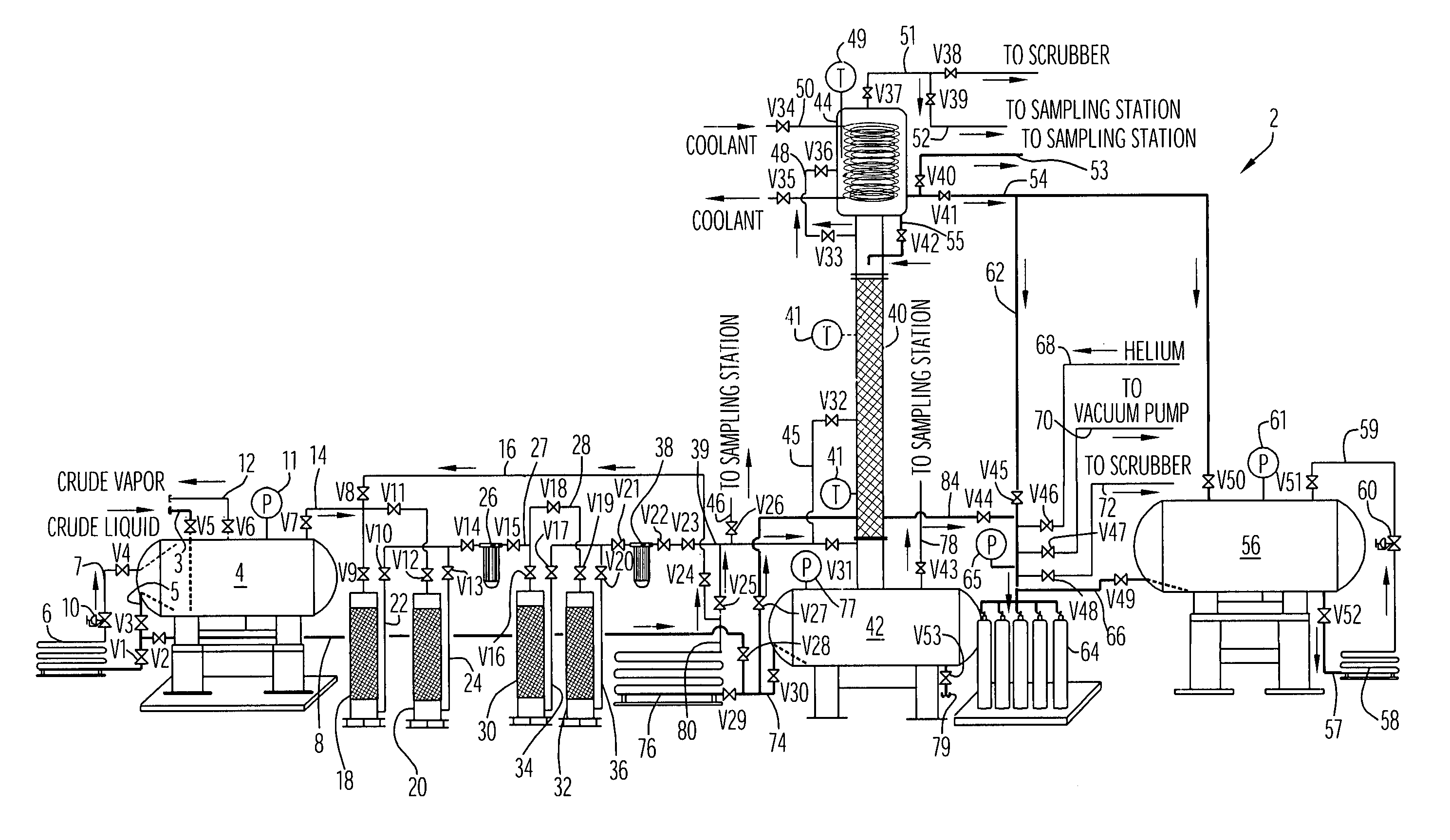
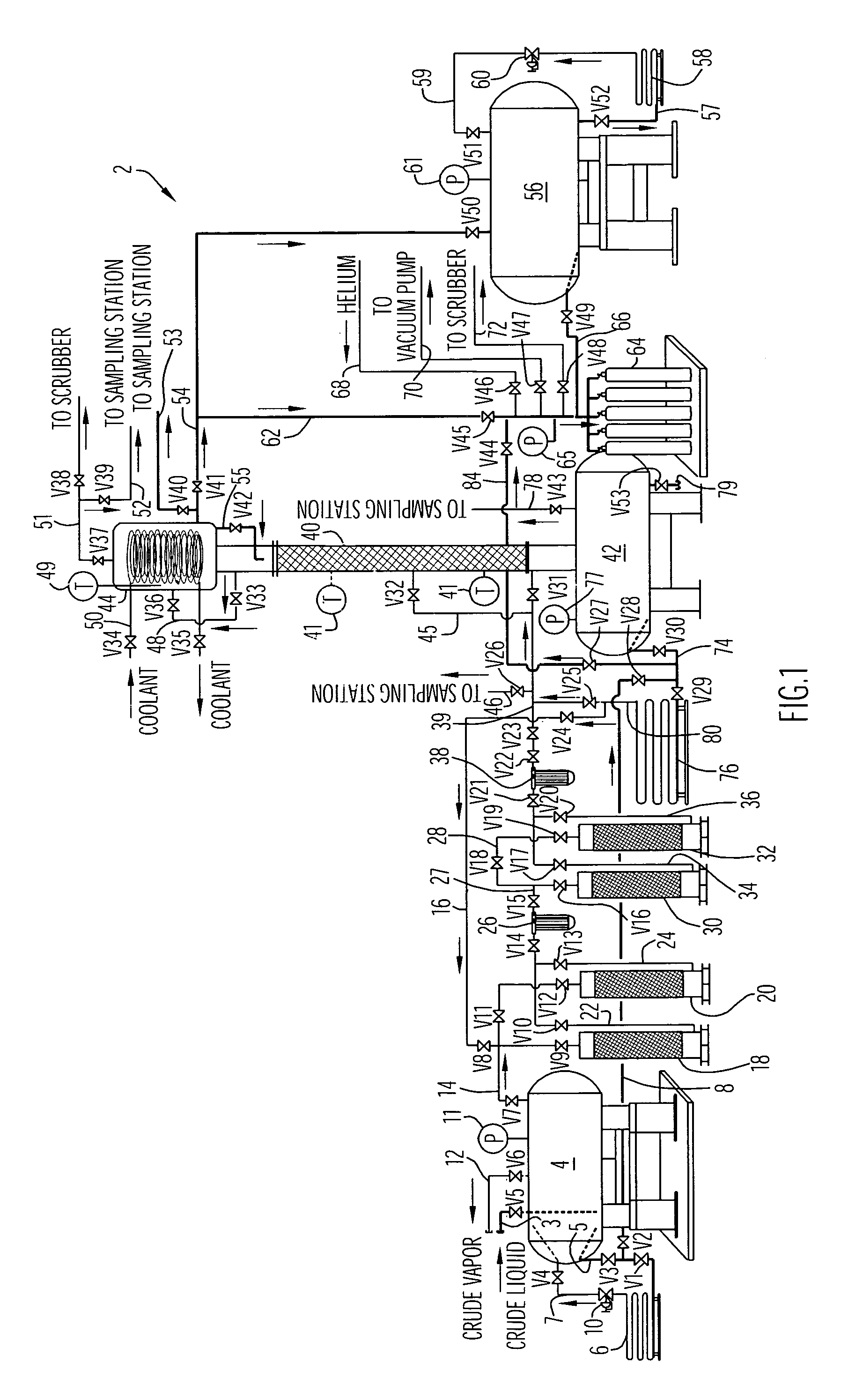
The present invention provides a system and method for purifying and transfilling ammonia at ultra-high purity levels. The system includes a hydrocarbon removal station, a moisture removal station, and a distillation column connected with a condenser to facilitate removal of impurities and condensation of gaseous ammonia. The system can maintain ammonia at ultra-high purity levels as it is delivered to a desired location. The invention also provides a medium transporting system for purging a fluid medium and a method of reconditioning a packed bed to increase its adsorbent capacity. The ammonia purification and transfilling processes and systems of the present invention are capable of purifying commercial grade ammonia feed supplied at varying purity levels to ultra-high purity levels.

Problems solved by technology

Even trace amounts of impurities present in the deposited films can deteriorate film quality and performance.
For example, trace amounts of oxygen in ammonia gas (e.g., 10 parts per billion (ppb) or less) used for manufacture of LED devices can cause lattice defects and are detrimental to band gap properties that are desirable for LED performance.
Trace impurities of other components in the ammonia gas, such as moisture or water, hydrocarbons and carbon oxides (e.g., carbon dioxide), are also detrimental and can lead to degradation of the final product if present in the nitride films being formed.
Further, certain impurities like moisture are very difficult to remove from ammonia gas to a sub parts per million (ppm) level.
At present, commercially available purifiers capable of removing moisture from ammonia at ppb levels are often very expensive and are not suitable for large scale processing flows of about 100 liters per minute (lpm) or greater.

Method used


Image

  • Purification and transfilling of ammonia
  • Purification and transfilling of ammonia

Examples


Embodiment Construction

[0022]In accordance with the present invention, an ammonia purification and transporting / transfilling system receives crude ammonia from a supply source (e.g., a supply tank) and includes a number of different purification units including, without limitation, adsorption units for removing hydrocarbons from ammonia, chemical sorption and adsorption units for removing water or moisture from ammonia, and one or more distillation units to remove light gas impurities from ammonia. The purification units can be arranged in the system in any suitable manner, with two or more of the same types of units being aligned in series and / or in parallel to facilitate processing of ammonia at multiple flow rates as well as maintaining system operation when one or more purification units are inactivated or brought offline (e.g., for regeneration of the units). The system is capable of purifying crude ammonia supplied at wide range of purity levels (e.g., 99.0% and lower) to ultra-high purity levels of...


PUM

PropertyMeasurementUnit
sizeaaaaaaaaaa
pore screen sizeaaaaaaaaaa
operating temperatureaaaaaaaaaa

Abstract

An ammonia purification system includes a hydrocarbon removal station that removes hydrocarbons from gaseous ammonia via adsorption, a moisture removal station that removes water from gaseous ammonia via adsorption, and a distillation station including a distillation column connected with a condenser to facilitate removal of impurities from ammonia and condensation of gaseous ammonia to form a purified liquid ammonia product. The system further includes a storage tank to receive purified ammonia, a remote station connected with the storage tank, and a vaporizer connected with the storage tank. The vaporizer is configured to receive and vaporize liquid ammonia from the storage tank and deliver gaseous ammonia back to the storage tank so as to facilitate pumping of the ammonia to the remote station based upon a vapor pressure established within the storage tank.

Description

CROSS-REFERENCE TO RELATED APPLICATIONS[0001]This application claims priority from U.S. Provisional Patent Application Ser. No. 60 / 586,028, entitled “System and Method For Purifying Ammonia and Ammonia Product Purified Thereby”, and filed Jul. 7, 2004. The disclosure of this provisional patent application is incorporated herein by reference in its entirety.BACKGROUND OF INVENTION[0002]1. Field of Invention[0003]The present invention pertains to methods and apparatus for purifying ammonia to obtain an ultra-pure ammonia product, particularly for use in semiconductor manufacturing and related applications.[0004]2. Related Art[0005]Ammonia is typically utilized in the manufacture of electronic devices such as semiconductor chips, light emitting diodes (LEDs) and flat panel display devices, as a source of nitrogen for depositing thin nitride films during formation of the particular device (e.g., tantalum nitride, titanium nitride, gallium nitride and silicon nitride). For example, in th...

Claims


Application Information

Patent Timeline
Patent Type & Authority Patents(United States)
IPC IPC(8): C01C1/02B01D53/04
CPCB01D53/02C01C1/024B01D53/261Y10S203/17C01C1/02C01C1/12F25J3/08
Inventor ZHOU, DERONGBORZIO, JOHN P.XU, MINDIWANG, HWA-CHIVUONG, TRAN
Owner AIR LIQUIDE AMERICA INC
Learn More