
Method of bonding a lenticular lens sheet to plastic objects and objects made from same

a technology of lenticular lens and plastic objects, which is applied in the field of plastic container and object manufacturing, can solve the problems of high temperature, deformation or ruination of ink, and achieve the effect of high quality and efficient and economical

Inactive Publication Date: 2005-03-10
TRAVEL TAGS
View PDF64 Cites 33 Cited by
  • Summary
  • Abstract
  • Description
  • Claims
  • Application Information

AI Technical Summary

Benefits of technology

"The invention provides a method to produce plastic objects with a unique Lenticular insert that includes optical ridges and air voids, which acts as an insulation layer and reduces heat transfer rates. The Lenticular insert is integrated into the outer wall of the object and can include gripping surfaces and animation clips. The method includes applying a protective substrate to the ink layer of the Lenticular insert to prevent damage during the plastic molding process. The resulting plastic object has high strength and durability, reduced material usage, and improved hoop strength. The framing system helps to hold the Lenticular insert in place and protect it from scratching and damage during handling. The fabrication method is efficient and cost-effective."

Problems solved by technology

Typical plastic fabrication processes, such as injection molding and blow molding, involve the heating of the raw plastic or charge material to high temperatures to make the plastic fluid or moldable but without further processes, these high temperatures would also degrade or ruin the ink.

Method used


Image

  • Method of bonding a lenticular lens sheet to plastic objects and objects made from same
  • Method of bonding a lenticular lens sheet to plastic objects and objects made from same
  • Method of bonding a lenticular lens sheet to plastic objects and objects made from same

Examples


Embodiment Construction

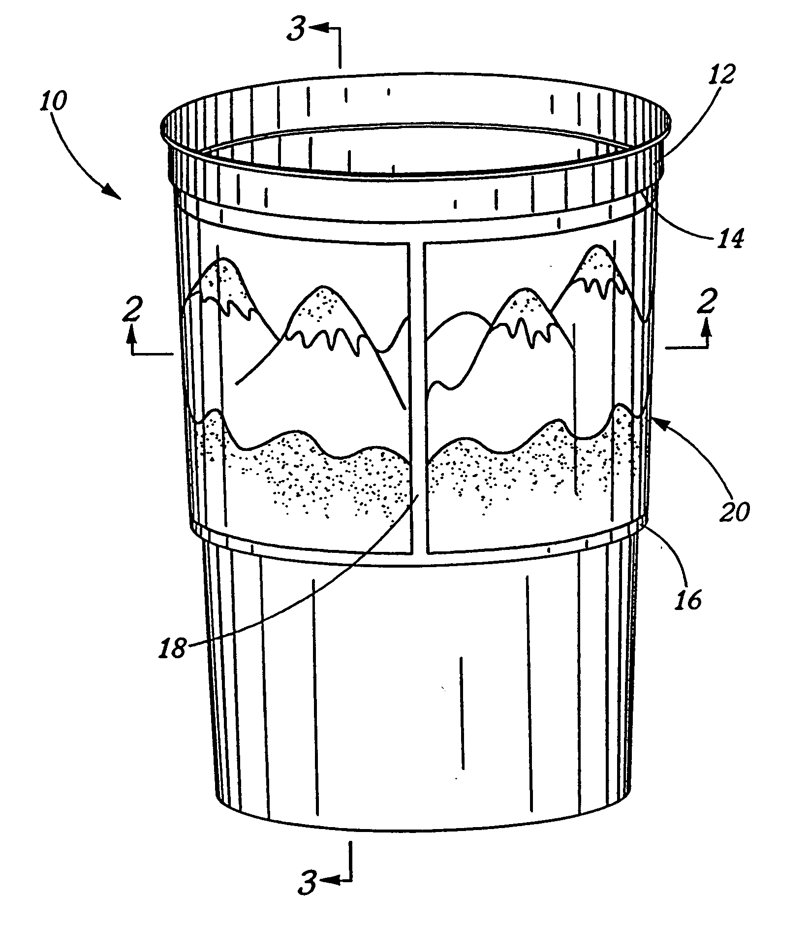
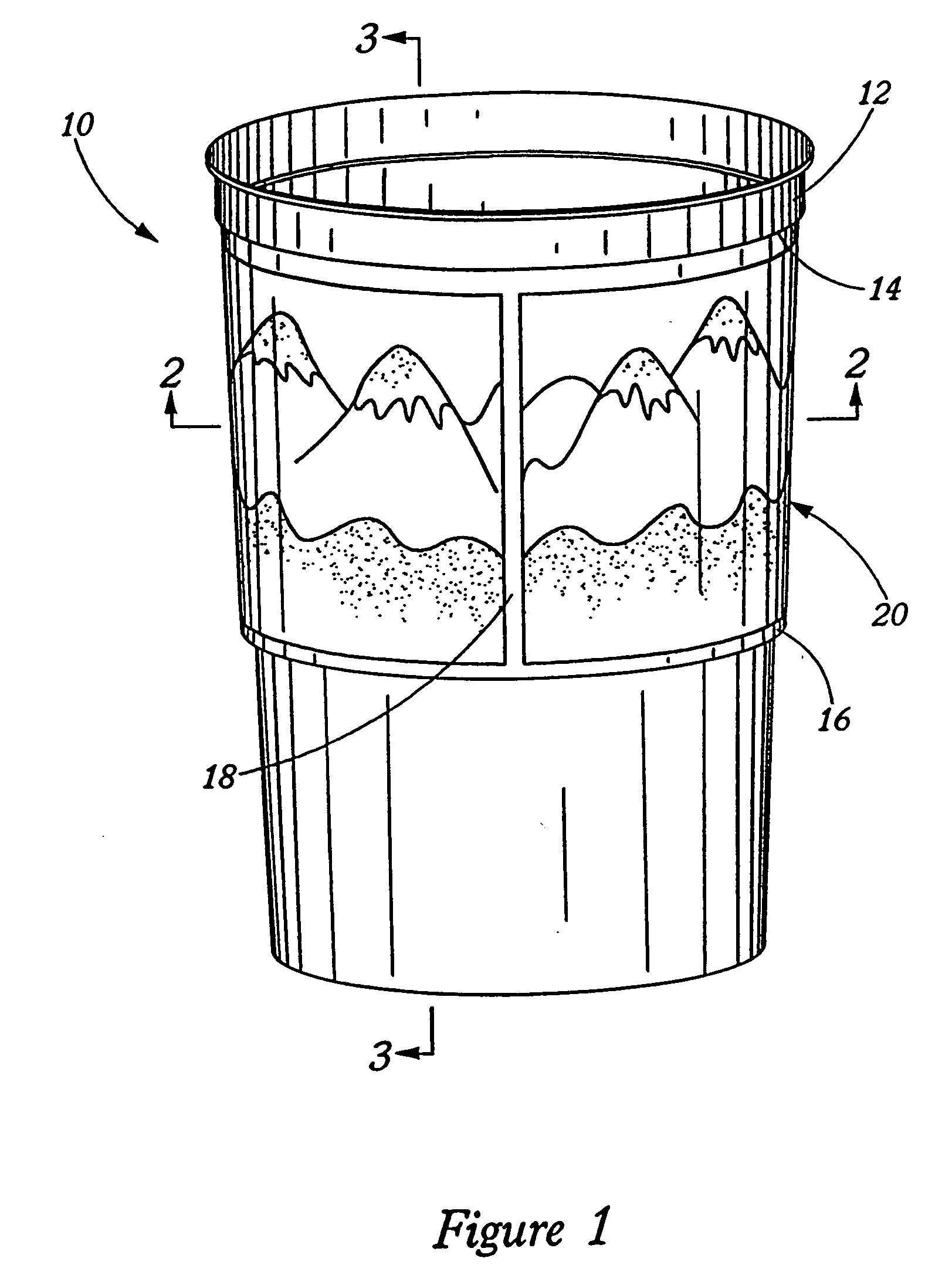
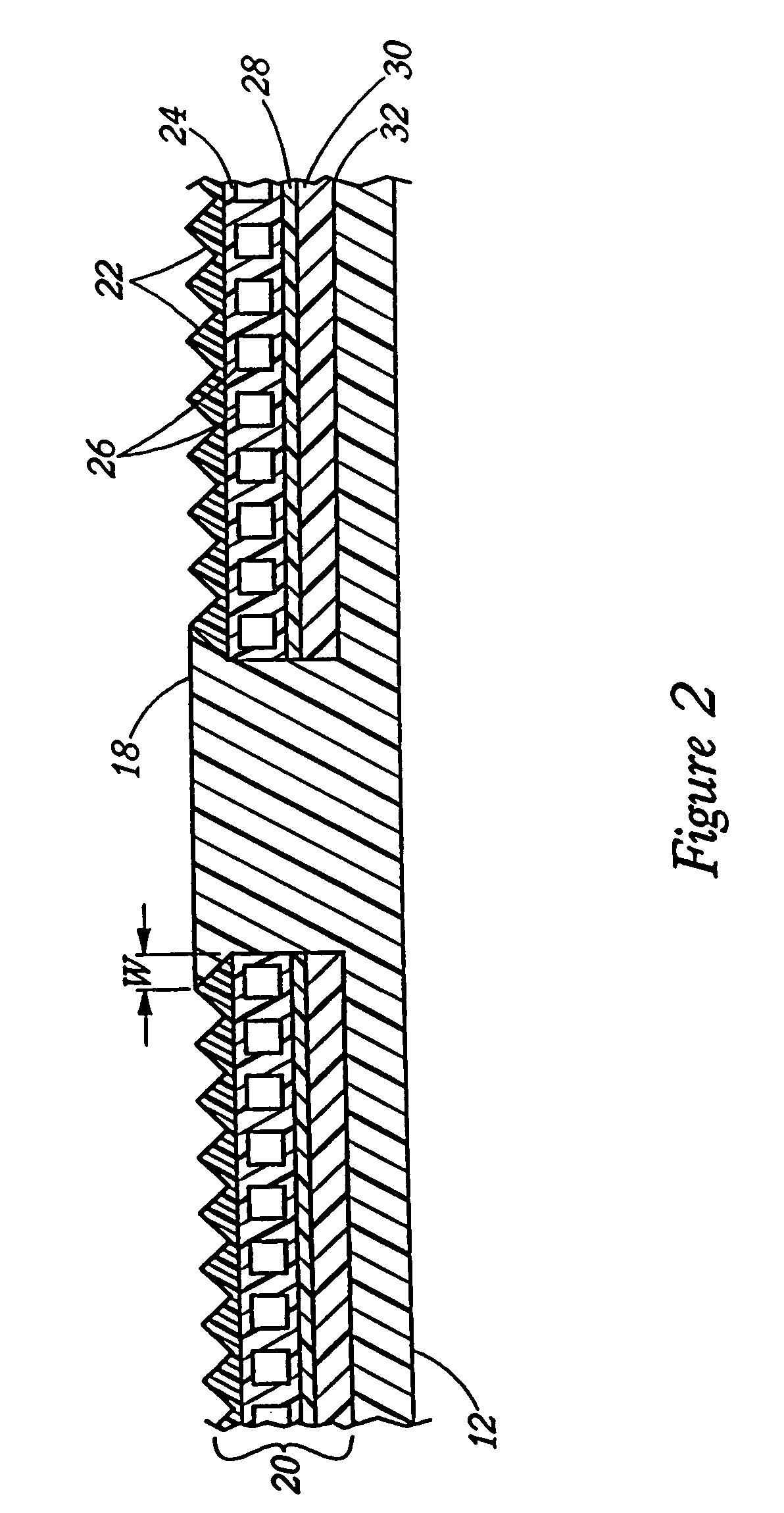
[0024] With the above summery of the invention in mind, the following description discusses the inventive plastic objects according to the invention that have an integral image visible due to a Lenticular insert that is uniquely included as an integral part of the plastic object. The discussion concentrates on the structural and other benefits and features of a container having a Lenticular insert in an outer wall, but, it should be understood that many other objects will similarly benefit from the addition of a Lenticular insert and are considered within the scope of the invention. From the discussion of features of a container fabricated according to the invention, the discussion proceeds to a full discussion of the method of fabricating plastic objects having a Lenticular insert integrally bonded to the plastic that forms the body, walls, or some other portion of the object. Again, the discussion will specifically explain the steps in fabricating a container with a Lenticular ins...


PUM

PropertyMeasurementUnit
temperatureaaaaaaaaaa

Abstract

A method of fabricating plastic objects having an insert of Lenticular lens material integrally bonded or otherwise attached therein. In one embodiment, the method is used to fabricate a container, such as a conical cup, by first manufacturing or providing a sheet of Lenticular material comprising layers of lens material and optical ridges and grooves and an ink layer printed on the flat side of the lens material. To protect the ink from the heat of molten or moldable plastic during later plastic processing, a thermally protective substrate is attached or bonded to the ink layer by using adhesives to attach a plastic substrate or by coating the ink with coating materials that thermally protect the ink from high temperatures. In one embodiment, the protective substrate is applied in a two step process of first placing a plastic hot melt onto a polyester or other material release liner and, after cooling of the hot melt, using heat and pressure to laminate or bond the hot melt plastic to the ink and then removing the liner. Lenticular inserts are cut out of the Lenticular material sheets and the inserts are positioned within a mold where the container is formed by injection, blow, or other molding process. In this step, the substrate acts as a bonding surface as it contacts the molten plastic, melts, and then cools forming a bonding interface with the plastic used to form the container.

Description

CROSS-REFERENCE TO RELATED APPLICATIONS [0001] This application refers to and specifically claims the benefit of U.S. Provisional Application No. 60 / 182,490, filed Feb. 15, 2000.FIELD OF THE INVENTION [0002] The present invention generally relates to the manufacture of plastic containers and objects, and more particularly, to a method of fabricating plastic objects having a lenticular lens sheet or insert. The fabrication method includes a process of bonding lenticular lens material to the constituent plastic of the container or object during molding processes without damaging the lenticular lens material. BACKGROUND OF THE INVENTION [0003] Throughout the world, it is a common and growing practice to utilize conventional plastic molded cups and containers to display promotional messages and to increase the market value of the cups and containers by adding images of sports figures, movie and television personalities, and other graphics. While the printing processes for producing thes...

Claims


Application Information

Patent Timeline
Patent Type & Authority Applications(United States)
IPC IPC(8): B32B1/00B29C45/14B29C49/20B29C49/24
CPCB29C45/14688Y10T428/1328B29C45/14836B29C49/20B29C49/24B29C2045/14696B29C2045/14704B29C2049/2412B29C2049/2472B29C2791/001B29K2995/0018B29K2995/002B29K2995/0026B29K2995/0087B29L2011/0016B29L2031/7132B29L2031/723B29L2031/744B65D2203/00Y10T428/1352Y10T428/1334Y10T428/2904Y10T428/13B29C45/14811Y10T428/31699
Inventor RAYMOND, MARK A.THORNBLOOM, BRUCE N.
Owner TRAVEL TAGS
Learn More