Charged Particle Microscope and Ion Microscope

Inactive Publication Date: 2013-05-23
HITACHI HIGH-TECH CORP
View PDF12 Cites 36 Cited by
  • Summary
  • Abstract
  • Description
  • Claims
  • Application Information

AI Technical Summary

Benefits of technology

[0045]According to the present invention, ionization gas utilization

Problems solved by technology

In addition, as for the electron beam, since the nature as a wave of electrons cannot be ignored, an aberration occurs due to

Method used


Image

  • Charged Particle Microscope and Ion Microscope
  • Charged Particle Microscope and Ion Microscope
  • Charged Particle Microscope and Ion Microscope

Examples


embodiment 1

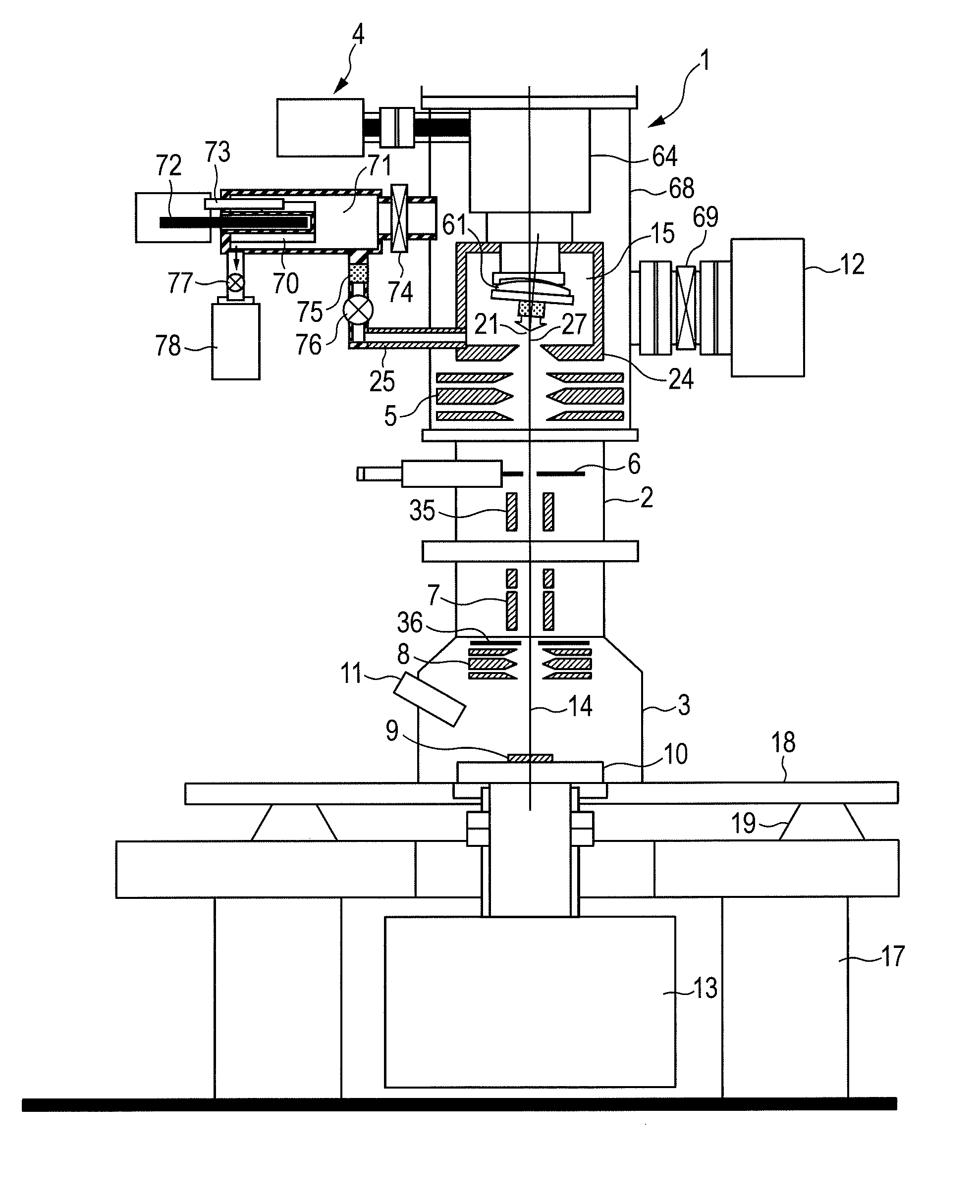
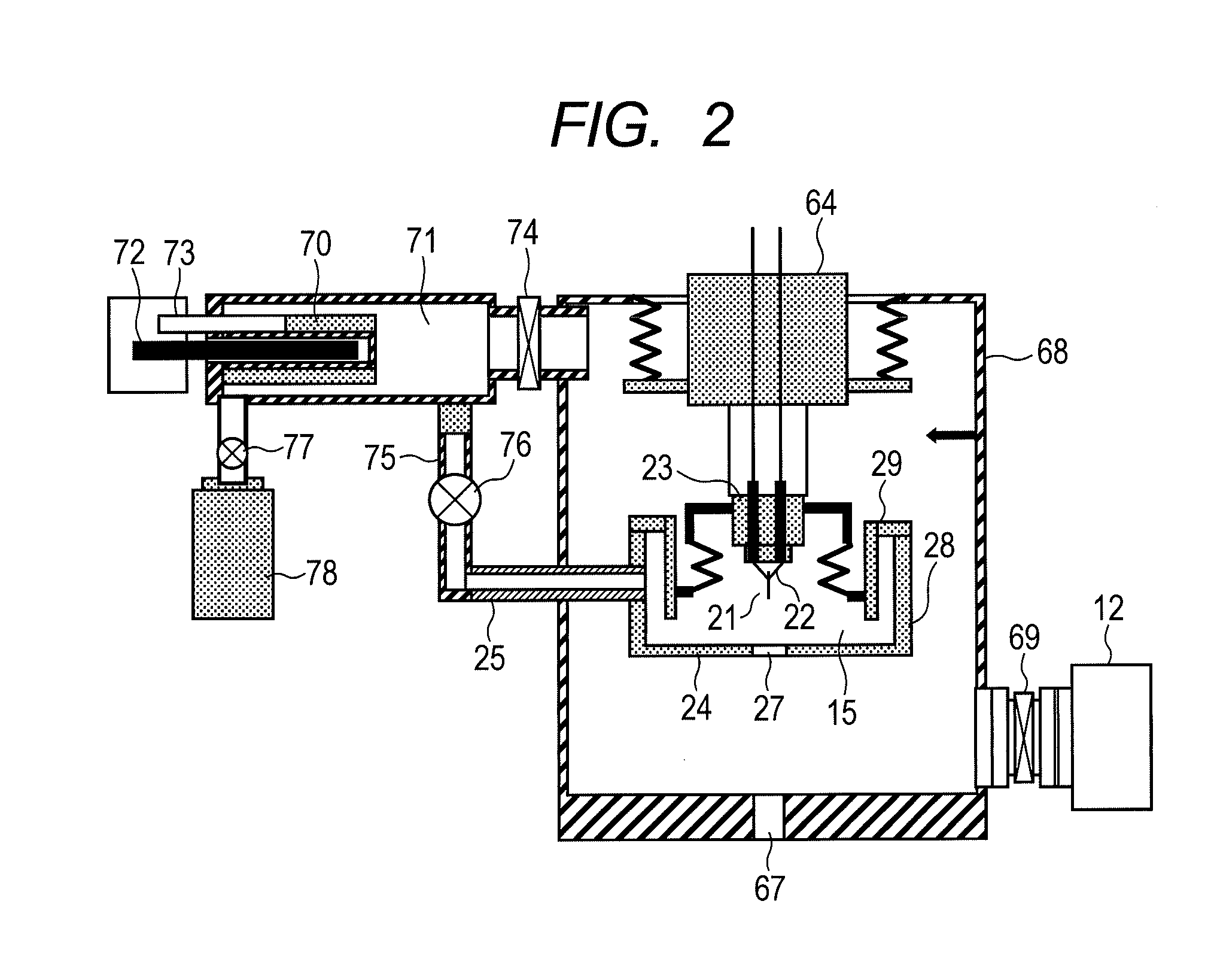
[0069]Referring to FIG. 1, an example of a charged particle microscope in accordance with the present invention will be described below. As an ion beam apparatus, a first example of a scanning ion microscope apparatus will be described. The scanning ion microscope of this example includes a gas field ion source 1, ion beam irradiation system column 2, sample chamber 3, and cooling mechanism 4. Herein, the interiors of the gas field ion source 1, ion beam irradiation system column 2, and sample chamber constitute a vacuum chamber.

[0070]The constitution of the gas field ion source 1 will be detailed later. In a vacuum chamber 68, an acicular emitter tip 21 and an extraction electrode 24 opposed to the emitter tip and having an opening 27 through which ions pass are incorporated. In addition, an ionization chamber 15 is formed in order to raise a gas pressure in the perimeter of the emitter tip.

[0071]Further, an ion source evacuation pump 12 that evacuates the vacuum chamber 68 of the ...

embodiment 2

[0122]Next, referring to FIG. 4, a description will be made of an embodiment in which at least two pairs of valves capable of performing vacuum blocking are each interposed between a vacuum chamber, which accommodates a material that adsorbs a gas which should be ionized, and a vacuum chamber in the aforesaid gas field ion source.

[0123]An iterative description of contents that overlap the contents of the embodiment 1 will be omitted.

[0124]In the present embodiment, as illustrated, on the left side of FIG. 4, a valve 74 capable of performing vacuum blocking is interposed between a vacuum chamber 71, which accommodates a material that adsorbs a gas which should be ionized, and a vacuum chamber. A way of using the material on one side that adsorbs the gas which should be ionized is identical to the aforesaid way of using. Specifically, a first non-evaporable getter 70 is heated in order to desorb a stored hydrogen gas, a membrane that selectively permeates the hydrogen gas is used to p...

embodiment 3

[0128]Next, referring to FIG. 5, a description will be made of a charged particle microscope that uses a hybrid particle source, which includes an emitter tip whose distal end is a nano-pyramid formed with atoms and has an ion beam or electrons extracted from the acicular emitter tip, to enable complex sample analysis based on observation of a sample surface, sample processing, and observation of a sample interior.

[0129]An iterative description of contents overlapping the contents of the embodiments 1 and 2 will be omitted.

[0130]A charged particle microscope of the present embodiment includes a hybrid particle source 301 that has an emitter tip whose distal end is a nano-pyramid formed with atoms and that extracts an ion beam or electrons from the acicular emitter tip, a hybrid irradiation system 302 that irradiates an electron beam or ion beam to a sample, a sample stage 303, a secondary particle detector 304 that detects secondary particles released from the sample, and an optical...


PUM


Abstract

In order to provide a safe and environmentally-friendly charged gas particle microscope that exhibits a superior ionized gas-utilization efficiency and economic efficiency, the gas field ion source of a charged particle microscope is equipped with a vacuum chamber in which are provided a vacuum chamber evacuation mechanism, an acicular emitter tip, an extraction electrode disposed facing the emitter tip, and a mechanism for supplying a gas to the vicinity of the emitter tip, and is configured so that the gas in the region around the tip of acicular ion emitter is ionized and extracted as an ion beam. Therein, the evacuation mechanism and the gas supply mechanism are connected, and a material for adhering the gas to be ionized is disposed between the evacuation mechanism and the gas supply mechanism.

Description

TECHNICAL FIELD[0001]The present invention relates to a charged particle microscope and ion microscope.BACKGROUND ART[0002]Electrons are irradiated to a sample while being swept in order to scan the sample, and secondary charged particles released from the sample are detected, whereby the structure of a sample surface can be observed. This is called a scanning electron microscope (hereinafter, abbreviated town SEM). In contrast, even when an ion beam is irradiated to the sample while being swept in order to scan the sample, and the secondary charged particles released from the sample are detected, the structure of the sample surface can be observed. This is called a scanning ion microscope (hereinafter, abbreviated to an SIM). In particular, when an ionic species of a small mass such as hydrogen or helium is irradiated to the sample, a sputtering effect gets relatively diminished. This is preferable for observation of the sample.[0003]Further, compared with an electron beam, an ion ...

Claims


Application Information

Patent Timeline
IPC IPC(8): H01J37/26
CPCH01J37/08H01J37/28H01J37/261H01J2237/0807H01J2237/006
Inventor SHICHI, HIROYASUMATSUBARA, SHINICHIOSE, YOICHIKAWANAMI, YOSHIMI
Owner HITACHI HIGH-TECH CORP
Why Eureka
Try Eureka