Method for improving blast furnace gas node pressure at user side

A technology of blast furnace gas and node pressure, which is applied to blast furnace details, blast furnaces, blast furnace parts, etc., can solve the problems of low calorific value and low pressure of gas, and achieve the increase of gas pressure and calorific value, obvious node pressure, The effect of nodal pressure stabilization

Pending Publication Date: 2021-12-24
NANJING IRON & STEEL CO LTD
View PDF4 Cites 0 Cited by
  • Summary
  • Abstract
  • Description
  • Claims
  • Application Information

AI Technical Summary

Problems solved by technology

[0004] The purpose of the present invention is to solve the problem of low pressure on the existing user side and the low calorific value of the gas, and provide a method for increasing the pressu

Method used


Image

  • Method for improving blast furnace gas node pressure at user side
  • Method for improving blast furnace gas node pressure at user side

Examples


Embodiment 1

[0021] In order to make the present invention clearer, a method for increasing the blast furnace gas node pressure at the user end of the present invention will be further described below. The specific embodiments described here are only used to explain the present invention, and are not intended to limit the present invention.

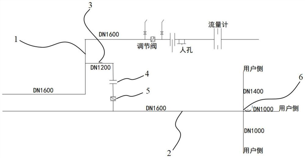
[0022] see figure 1 , a method for increasing the pressure of a blast furnace gas node at a user end, comprising a converter gas main pipeline and a blast furnace gas main pipeline, the specific operation steps are as follows, and it is characterized in that:

[0023] Connect a converter gas branch pipe DN1200 from the end of the converter gas main pipe DN1600, the maximum gas delivery capacity of the main pipe is 101000m³ / h, and the branch pipe delivery capacity is 56000m³ / h;

[0024] Install a pair of flanges on the branch pipe of converter gas, which is used to isolate blast furnace gas and converter gas during maintenance, for easy maintenance, an...


PUM


Abstract

The invention relates to a method for improving blast furnace gas node pressure at a user side. The method comprises the following steps of connecting a converter gas branch pipe (3) with the tail end of a converter gas main pipeline (1), installing a pair of flanges (4) on the converter gas branch pipe (3), installing an adjusting butterfly valve (5) behind the flanges (4), and after adjustment, feeding converter gas into a blast furnace gas main pipeline (2), wherein mixed gas in the pipeline is conveyed straight to a bar and a secondary burning node (6), and the calorific value of the gas is increased to 900 kilocalories/Nm < 3 >. Meanwhile, due to the fact that converter gas is mixed with the blast furnace gas, the use amount of blast furnace gas for sintering and the pressure loss of the pipeline are reduced, and the pressure of an end user is increased. The method has the advantages that the nearby converter gas is fully utilized, and the utilization efficiency of the gas is improved while production operates stably.

Description

technical field [0001] The invention relates to the technical field of sintering machines, in particular to a method for increasing the blast furnace gas node pressure at a user end. Background technique [0002] The sintering machine of 220 sintering uses blast furnace gas as fuel, and the blast furnace gas is sent from the blast furnace gas pipeline in the No. Under the viaduct of 200,000 cabinets, it is connected with the gas pipeline of 200,000 cabinets in No. 1 Iron Works, and a pipe is connected to the medium rod workshop in the middle; the other road is erected along the concentric road through the steel avenue overhead pipe gallery, and the pressure is adjusted by the new steelmaking Station, the coal injection workshop of the No. 2 Iron Works, and the bars reach the sintering area of ​​220, and are sent to the sintering machine through the gas pipeline in the sintering area. Branch pipes are connected to the coal injection and the bars for the use of two users. [...

Claims


Application Information

Patent Timeline
IPC IPC(8): C22B1/16C21B7/00C21C5/38
CPCC22B1/16C21B7/002C21C5/38C21C2100/06C21B2100/80C21B2100/62
Inventor 孙雯胡楠
Owner NANJING IRON & STEEL CO LTD
Why Eureka
Try Eureka