Process and apparatus for applying optical coatings

a technology of optical coatings and apparatuses, applied in vacuum evaporation coatings, electrolysis components, coatings, etc., can solve the problems of reduced adhesion, reduced suitability, and possible even flaking off of layers,

Active Publication Date: 2010-10-26
SATISLOH AG
View PDF7 Cites 0 Cited by
  • Summary
  • Abstract
  • Description
  • Claims
  • Application Information

AI Technical Summary

Benefits of technology

[0012]The process according to the invention and the apparatus according to the invention are used to apply an optical transition layer to a front surface of a substrate. The transition layer is intended to match mechanical properties of the substrate to mechanical properties of layers or layer systems which are to be applied above the transition layer. This produces compatibility between the materials of the substrate and the layers above it in terms of their elasticity, hardness and thermal properties.
[0013]Sputtering forms the basic process for the application of the transition layer. Sputtering offers the advantage of quickly building up the layer in combination with an excellent directional characteristic, with the result that contamination of the vacuum chamber is substantially prevented. During the sputtering operation used to build up the transition layer, precursors whereof the reaction products, in the state in which they are incorporated in the transition layer, alter the mechanical properties of the transition layer are introduced into the vacuum chamber. The concentration of the precursors, which are in a vapor phase, in the vacuum chamber is set in such a manner that the deposition of reaction products and / or precursors without a simultaneous sputtering operation, i.e. as part of the CVD process, is substantially prevented or does not take place. This means that, with regard to the reaction products and precursors, without a sputtering operation taking place adsorption and desorption are in equilibrium, whereas during the sputtering operation the desorption is impeded and / or adsorption promoted on the regions which lie opposite the target, in particular the surfaces which are to be coated. In this way, reaction products and / or precursors are deposited in a targeted way and at least virtually exclusively in the region lying opposite the target, in particular on the front surfaces of the substrates; there is much less contamination of the surrounding surfaces in the vacuum chamber and the rear side of the substrate.

Problems solved by technology

However, inorganic layers have the drawback of generally being very brittle, which means that they are of only limited suitability, for example, for application to plastic substrates with different mechanical and / or thermal properties, in particular an elasticity and expansion coefficient which are different from those of the inorganic layer.
Major differences in the mechanical and / or thermal properties of the substrate and functional layer lead to reduced adhesion and possibly even to the layers flaking off.
Layers flaking off spectacle lenses, for example, may lead to vision being impaired when wearing the spectacles.
However, these hard lacquer coating operations are very technically complex, produce only a low yield of optically perfect hard lacquer layers and have a relatively low resistance to abrasion and weathering compared to the inorganic layers applied by means of vacuum coating processes, such as oxide or nitride layers.
Furthermore, a two-stage production process of this type entails increased costs on account of possible surface contamination and more complex handling techniques.
A disadvantage which has emerged with plasma-enhanced CVD processes is that not only the desired surfaces of a substrate but also other surfaces in the vacuum chamber, in particular including rear sides of the substrates, are coated or contaminated in an uncontrolled way.
Accordingly, time-consuming and expensive cleaning work has to be carried out on the vacuum chamber during the production process.
Since uncontrolled coating of the rear side affects the optical quality of the end product, CVD processes of this type cause problems with the production of optical elements.
However, this process is technically complex and does not sufficiently prevent contamination of the vacuum chamber and uncontrolled coating of the rear side of the substrates.

Method used


Image

  • Process and apparatus for applying optical coatings
  • Process and apparatus for applying optical coatings

Examples


Embodiment Construction

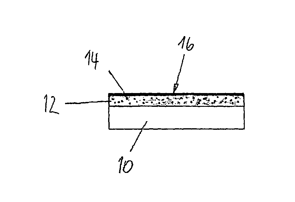
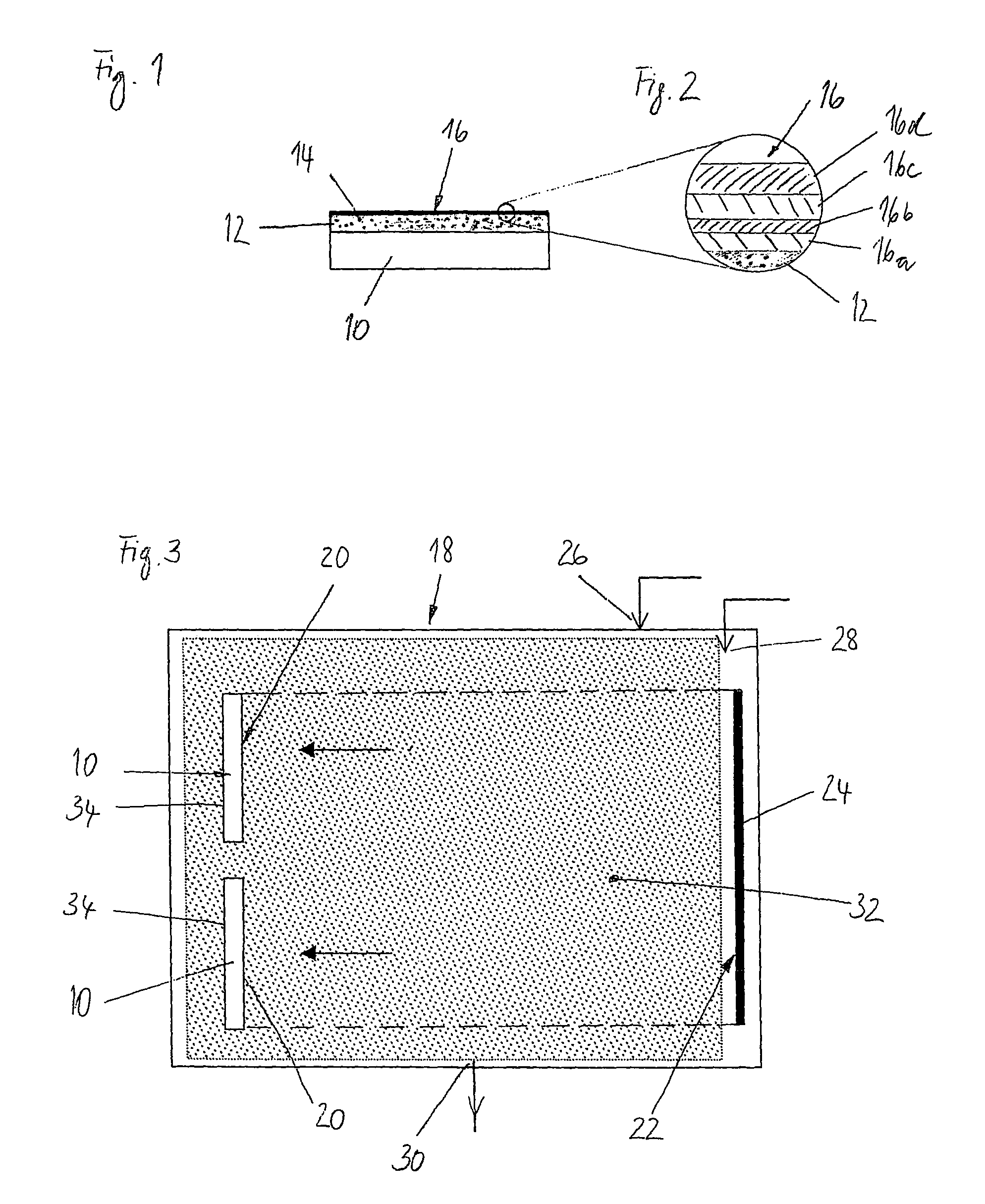
[0020]FIG. 1 shows a substrate 10 with a coating which has been produced using the process according to the invention or by means of the apparatus according to the invention. A transition layer 12 (also referred to as a hard layer), in which reaction products 14 formed from precursors are incorporated, has been produced directly above the substrate 10. The reaction products 14 are used to match the mechanical and thermal properties of the substrate 10 to the mechanical and thermal properties of an antireflection layer system 16 above it. This ensures that the substrate 10 is mechanically compatible with the layer system 16. An increased elasticity and therefore improved matching of the transition layer 12 prevents the generally very brittle, inorganic layer system 16 from becoming detached. Therefore, the transition layer performs a bridging function between the substrate 10 and the layer system 16.

[0021]The transition layer 12 which is shown in FIG. 1, has been applied to a substra...


PUM

PropertyMeasurementUnit
partial pressureaaaaaaaaaa
distanceaaaaaaaaaa
distanceaaaaaaaaaa

Abstract

A process and apparatus for applying an optical coating to a substrate, wherein a transition layer 12, which is used to match mechanical properties of a substrate 10 to mechanical properties of a layer system 16 to be applied upon the transition layer 12, is deposited on a front surface 20 of the substrate 10. For this purpose, during a sputtering process carried out in a vacuum chamber 18, reaction products 14 are incorporated at least virtually exclusively in the transition layer 12 on the substrate. This prevents other surfaces of the vacuum chamber 18 and the rear side 34 of the substrate 10 from being contaminated with the reaction products 14 and / or their precursors.

Description

BACKGROUND OF THE INVENTION[0001]The invention relates to a process and an apparatus for applying an optical coating to a front surface of a substrate located in a vacuum chamber.[0002]A range of vacuum coating processes are used to produce optical coatings, for example for antireflection and mirror coatings, optical filters and other treatments of substrate surfaces. The vacuum coating processes carried out in a vacuum chamber include, inter alia: vapor deposition (VD), chemical vapor deposition (CVD) and sputtering (physical vapor deposition—PVD).[0003]During vapor deposition, first of all a coating material is melted and vaporized by means of a heater or electron beam bombardment. The material in the vapor phase then condenses on a cooler surface of the substrate which is to be coated, where it forms a layer. However, deposits are also formed on other surfaces of the vacuum chamber which are accessible to the vapor phase.[0004]Unlike in the case of physical vapor deposition proce...

Claims


Application Information

Patent Timeline
Patent Type & Authority Patents(United States)
IPC IPC(8): C23C14/34
CPCC23C14/0057C23C14/024C23C14/04C23C14/34
Inventor BREME, FRANK
Owner SATISLOH AG
Why Eureka
Try Eureka