
Muscle stimulation device

a technology of muscle stimulation and muscle, applied in the field of muscle stimulation devices, can solve the problem of no further possibilities for use or training

Active Publication Date: 2015-11-03
TREMO TEC GMBH
View PDF11 Cites 2 Cited by
  • Summary
  • Abstract
  • Description
  • Claims
  • Application Information

AI Technical Summary

Benefits of technology

The invention is a muscle stimulation device that uses a dumbbell with a vibrating bar. The device has eccentric bodies that are arranged in a way that their center of mass is located at different distances from the ends of the handle bar. This results in different strengths of vibrations on each end of the handle bar. This design allows the device to be used as a training device or a therapeutic or massage device, where the vibrations can be transferred to a specific part of the body. This design also improves the efficiency of muscle stimulation compared to previous dumbbells.

Problems solved by technology

The dumbbell known from DE 195 32 254 C1 is well suited as a training device for an accelerated building up of the biceps and triceps muscles, however, it offers no further possibilities for use or training.

Method used


Image

  • Muscle stimulation device
  • Muscle stimulation device
  • Muscle stimulation device

Examples


Embodiment Construction

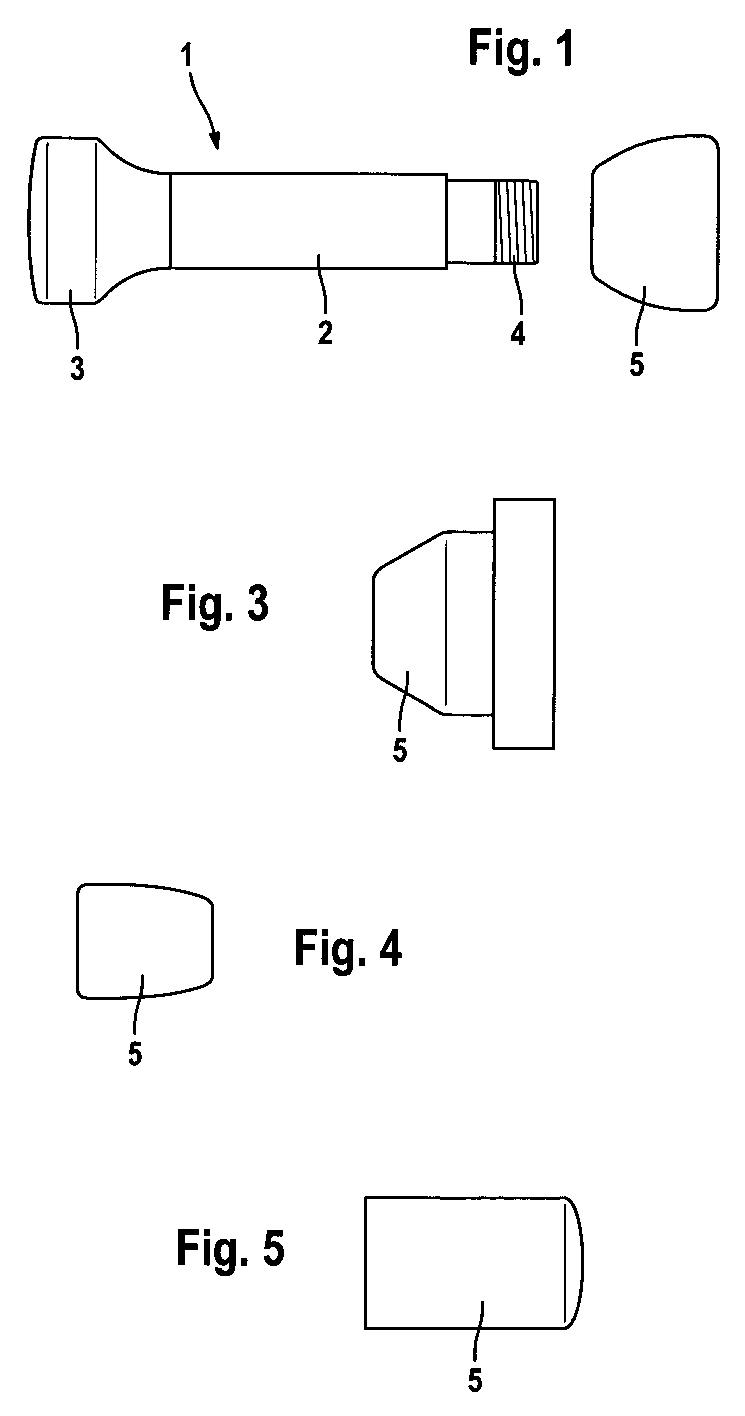
[0021]The muscle stimulation device 1 depicted in FIG. 1 comprises a handle bar 2, onto the first end of which a head 3 is affixed by material connection. On the second end of the handle bar 2 there is a connecting element 4 to affix an exchangeable head 5. In the exemplary embodiment depicted, the connecting element 4 is designed as an external thread which, together with an appropriate counterpart of the exchangeable head 5, forms a screw connection. Alternatively, with an appropriate counterpart of an exchangeable head 5, the connecting element 4 can, however, also form a plug connection or a bayonet joint, in particular a bayonet lock, and be formed correspondingly.

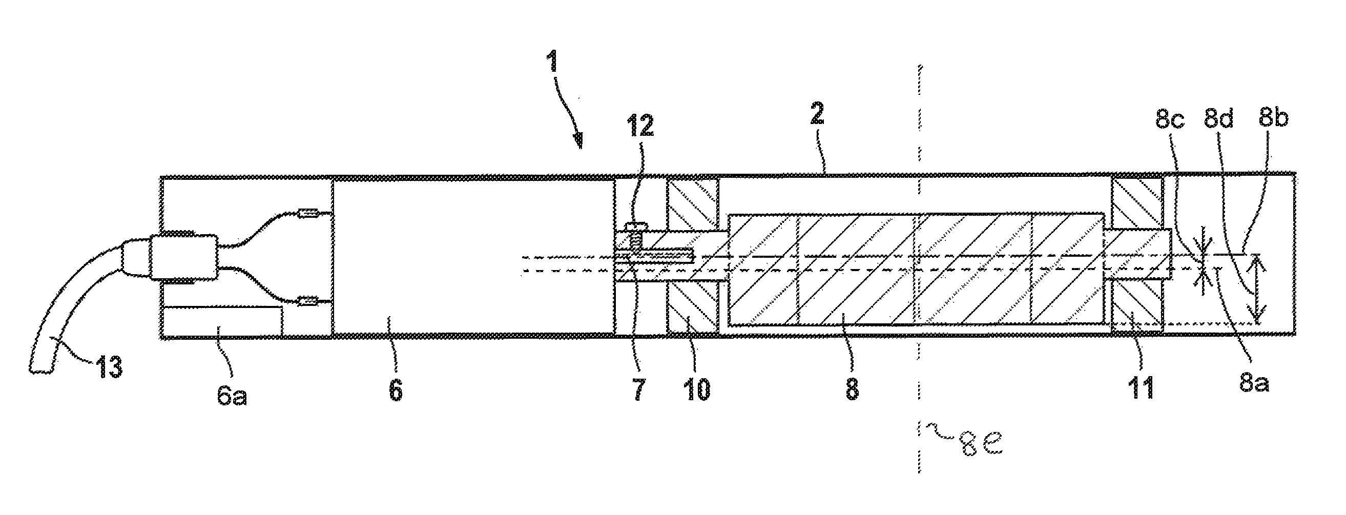
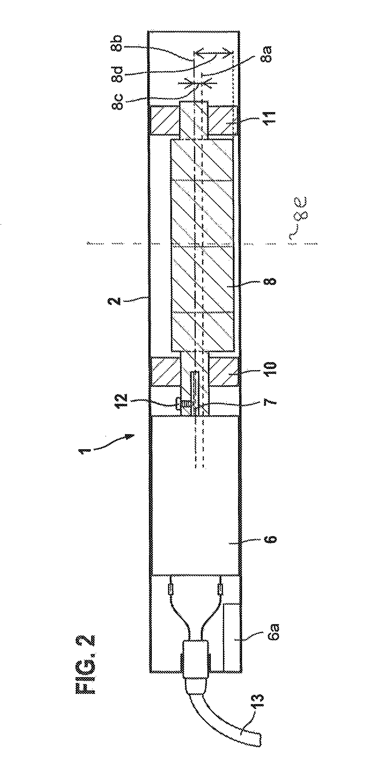
[0022]In FIG. 2, a section of the handle bar 2 of the muscle stimulation device 1 is depicted in a schematic longitudinal section view. The handle bar 2 designed as a tube contains a cavity in which a motor 6 is arranged which is coupled to an eccentric body 8 by means of a motor shaft 7, in order to set the muscle st...


PUM


Abstract

The invention relates to a muscle stimulation device comprising a handle bar with a first and a second end, a motor which is arranged in a cavity in the handle bar and is coupled by means of a motor shaft to at least one eccentric body in order to set the muscle stimulation device vibrating by an unbalance of the eccentric body. According to the invention the eccentric body / ies has / have a common center of mass, which is at a different distance from the first end of the handle bar than it is from the second end of the handle bar. The invention furthermore relates to an exchangeable head for such a muscle stimulation device.

Description

[0001]The invention relates to a muscle stimulation device comprising a handle bar with a first and a second end, as well as a motor which is arranged in a cavity of the handle bar and is coupled by means of a motor shaft to at least one eccentric body in order to set the muscle stimulation device vibrating by an unbalance of the eccentric body.[0002]A dumbbell with a vibrating bar is known from DE 195 32 254 C1, in which there are a motor and two eccentric bodies arranged symmetrically in relation to the ends of the dumbbell bar. By rotating the eccentric bodies, the dumbbell bar is set vibrating, wherein disc-shaped weights attached to the dumbbell bar are decoupled from the vibration of the dumbbell bar by an interlayer of vibration absorbers. During training with this kind of dumbbell, vibrations of the dumbbell bar transfer onto muscle parts being used, and stimulate nerves coordinating motions. This leads to a faster building up of muscles than in training with conventional du...

Claims


Application Information

Patent Timeline
Patent Type & Authority Patents(United States)
IPC IPC(8): A61H1/00A63B21/072A63B21/00
CPCA63B21/072A61H1/00A63B21/00196A63B21/15A63B21/4017A63B21/0004A63B2230/00
Inventor BERGER, MARCBERGER, THOMAS
Owner TREMO TEC GMBH
Learn More