
Transmission device having a hydraulic system

a transmission device and hydraulic system technology, applied in mechanical equipment, gearing details, gearing, etc., can solve the problems of short-term under-supply states in the cooling circuit of the gear set, high manufacturing costs, and inability to compensate short-term under-supply states

Active Publication Date: 2019-01-22
ZF FRIEDRICHSHAFEN AG
View PDF15 Cites 2 Cited by
  • Summary
  • Abstract
  • Description
  • Claims
  • Application Information

AI Technical Summary

Benefits of technology

This patent describes a transmission device designed to improve the cooling of the gears in a cost-effective way, while avoiding the need for excessive hydraulic fluid. The device uses a valve to control the flow of hydraulic fluid to the gears, allowing for a more precise control over cooling during operation. This design also allows for a faster buildup of system pressure during the starting process of the drive unit.

Problems solved by technology

In addition to the main pump, the hydraulic control unit features an auxiliary pump, which is characterized by high manufacturing costs and is driven by an electric motor.
However, the supply of a cooling system of a gear set of the toothed wheel change-gear transmission, designed as a dual-clutch transmission, starting from the auxiliary pump then to be driven by the allocated electric motor, can only be realized by a corresponding actuation of the control, which is why short-term under-supply states in the area of the cooling circuit of the gear set cannot be compensated by the auxiliary pump with the desired spontaneity.

Method used


Image

  • Transmission device having a hydraulic system
  • Transmission device having a hydraulic system
  • Transmission device having a hydraulic system

Examples


Embodiment Construction

[0047]Reference will now be made to embodiments of the invention, one or more examples of which are shown in the drawings. Each embodiment is provided by way of explanation of the invention, and not as a limitation of the invention. For example, features illustrated or described as part of one embodiment can be combined with another embodiment to yield still another embodiment. It is intended that the present invention include these and other modifications and variations to the embodiments described herein.

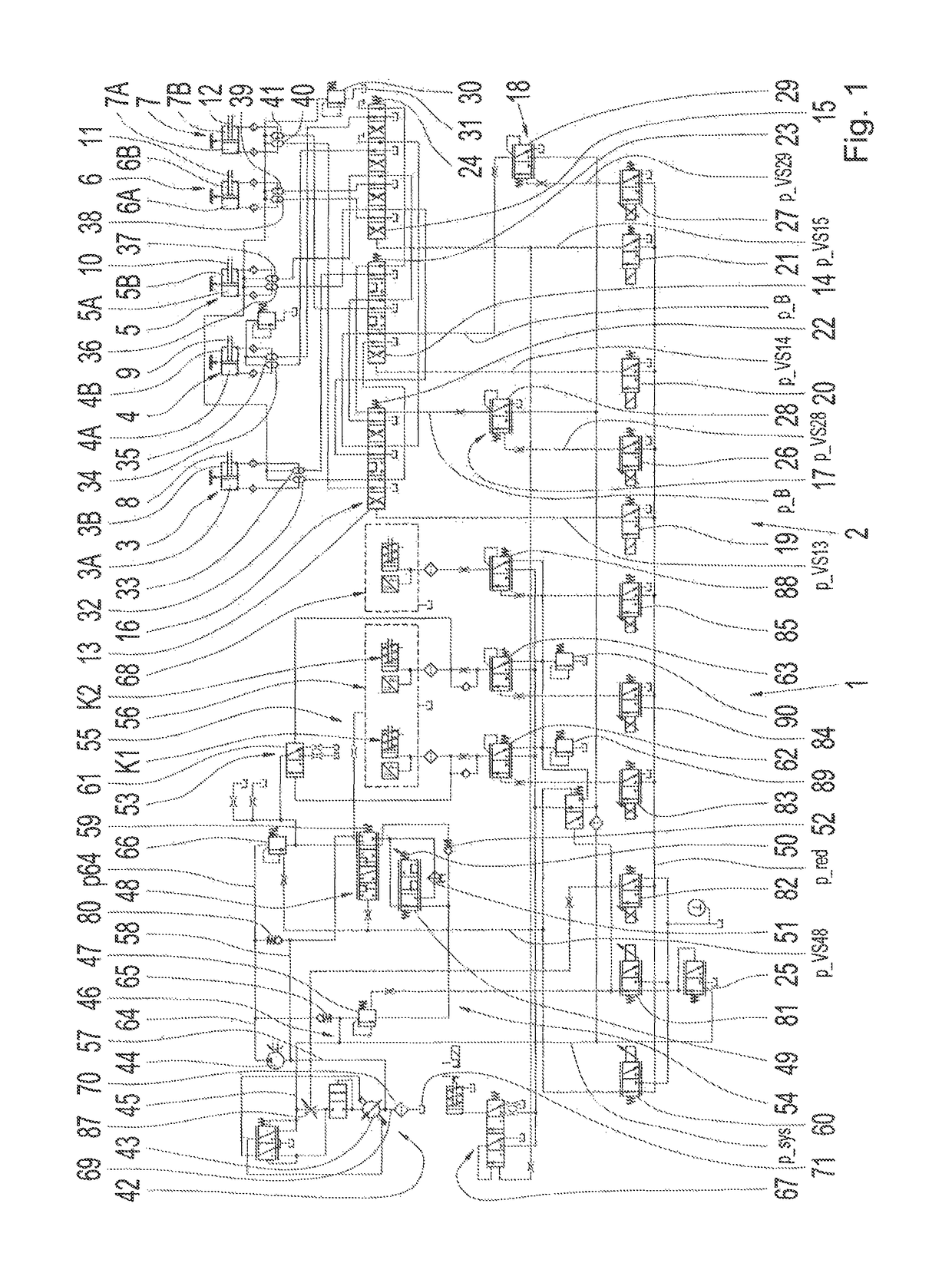
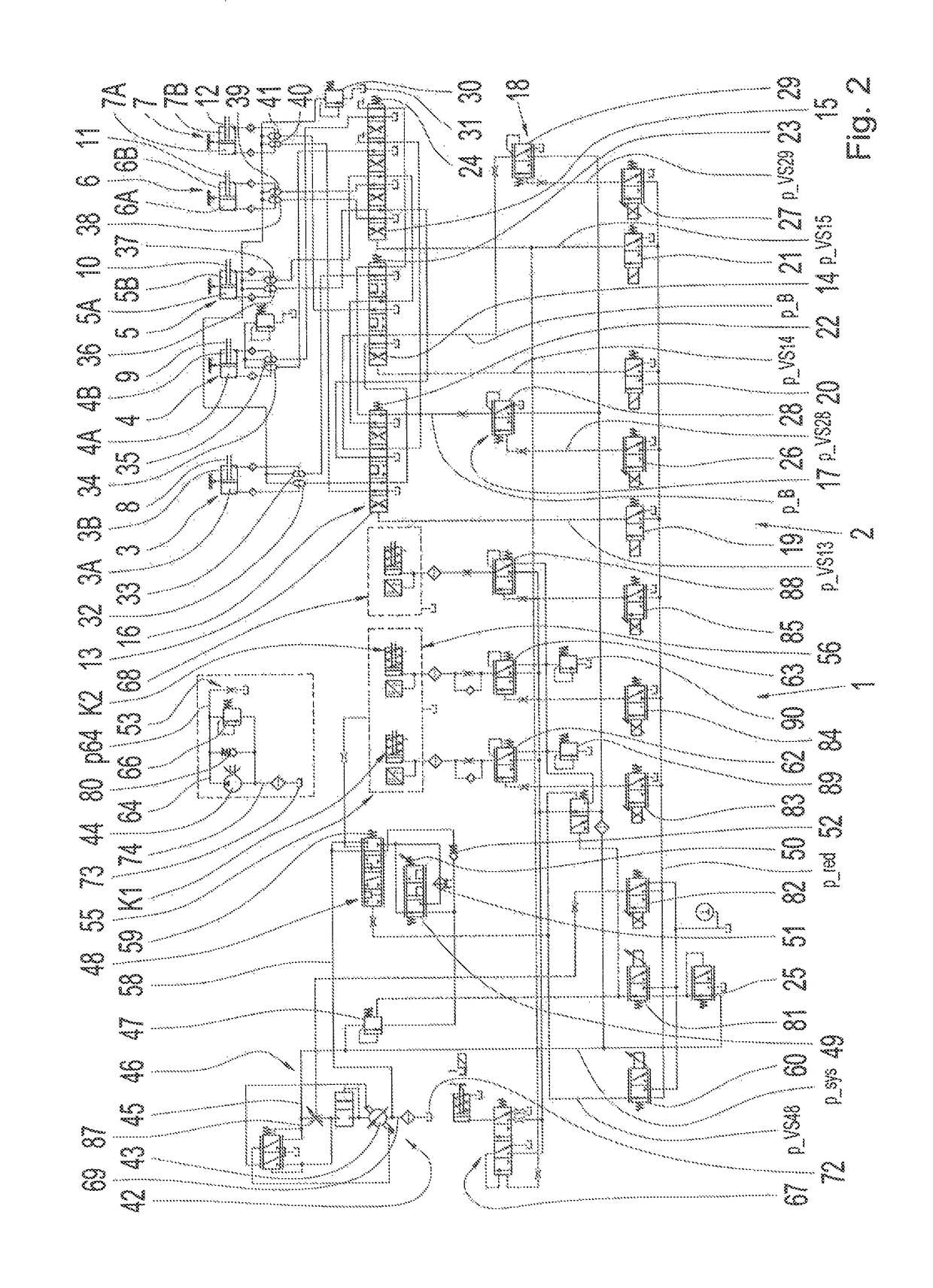
[0048]FIG. 1 shows a hydraulic diagram of a hydraulic system 1 or a hydraulic actuating device of a transmission device 2 or a transmission, as the case may be, which is designed as a dual-clutch transmission, in which nine transmission ratios for forward travel and one transmission ratio for reverse travel can be engaged. The transmission ratios can be engaged and disengaged by the hydraulically actuated piston / cylinder devices 3 through 7 and adjustable shifting elements 8 throu...


PUM


Abstract

A transmission includes a hydraulic system connected to a hydraulic pump and to an additional hydraulic pump. A secondary pressure circuit is connectable to a primary pressure circuit with a system pressure valve. A pressure side of the hydraulic pump is coupled directly with the primary pressure circuit and connectable to the secondary pressure circuit with the system pressure valve. A pressure side of the additional hydraulic pump is coupled directly with the secondary pressure circuit. The pressure side of the hydraulic pump proximate the secondary pressure circuit is connectable to a gear set, to a dual-clutch system and to a suction area of the hydraulic pump and the additional hydraulic pump by a valve device. The pressure side of the additional hydraulic pump is in connection with the gear set and is connectable with the dual-clutch system by the valve device.

Description

FIELD OF THE INVENTION[0001]The invention relates generally to a transmission device with a hydraulic system.BACKGROUND[0002]DE 10 2011 077 552 A1 discloses a hydraulic configuration for a transmission, by which the supply of a hydraulic medium of components of a vehicle's transmission can be carried out. The hydraulic configuration includes at least one main pump device driven on the drive side for supplying a primary hydraulic circuit with a primary pressure, and is additionally designed with at least one auxiliary pump that can be driven on the output side, which is provided for supplying a secondary hydraulic circuit with a secondary pressure. The auxiliary pump device is connected either directly to the primary hydraulic circuit or directly to the secondary hydraulic circuit, whereas a coupling device is provided for coupling the auxiliary pump device to the output of the transmission or a switching-on device for opening the hydraulic medium supply of the auxiliary pump device ...

Claims


Application Information

Patent Timeline
Patent Type & Authority Patents(United States)
IPC IPC(8): F16H61/4008F16H61/00F16H61/02F16H61/06F16H61/688F16H57/04F16H3/00F16H61/28
CPCF16H61/688F16H3/006F16H57/0435F16H57/0441F16H61/0025F16H61/0206F16H57/0446F16H2061/0037F16H61/2807
Inventor NOVAK, RAINERPFLEGER, TOBIAS
Owner ZF FRIEDRICHSHAFEN AG
Learn More