Frictional shifting element for a vehicle transmission

a technology of shifting element and transmission, which is applied in the direction of friction clutch, mechanical actuated clutch, clutch, etc., can solve the problems of clearance in the entire multi-disk pack, and achieve the effect of cost-effective manufacturing and low drag torqu

Active Publication Date: 2018-01-02
ZF FRIEDRICHSHAFEN AG
View PDF22 Cites 6 Cited by
  • Summary
  • Abstract
  • Description
  • Claims
  • Application Information

AI Technical Summary

Benefits of technology

[0004]Exemplary aspects of the present invention provide a frictional shift element for a transmission of a motor ve

Problems solved by technology

This results in a clearance i

Method used


Image

  • Frictional shifting element for a vehicle transmission
  • Frictional shifting element for a vehicle transmission
  • Frictional shifting element for a vehicle transmission

Examples


Embodiment Construction

[0032]Reference will now be made to embodiments of the invention, one or more examples of which are shown in the drawings. Each embodiment is provided by way of explanation of the invention, and not as a limitation of the invention. For example, features illustrated or described as part of one embodiment can be combined with another embodiment to yield still another embodiment. It is intended that the present invention include these and other modifications and variations to the embodiments described herein.

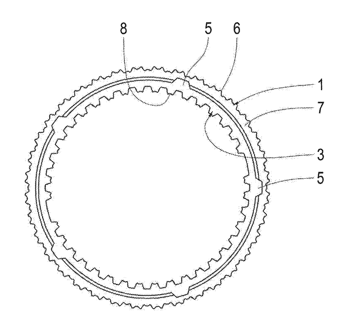
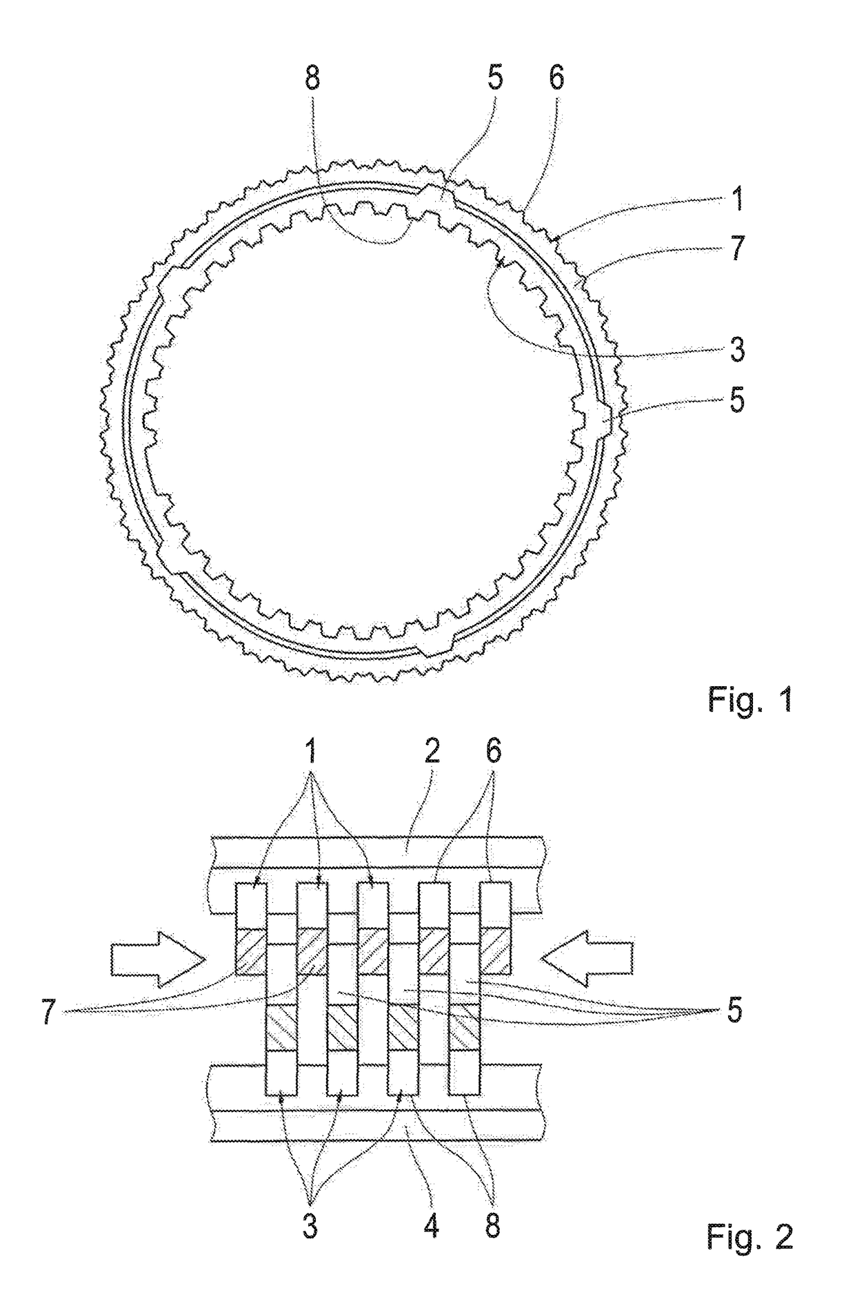
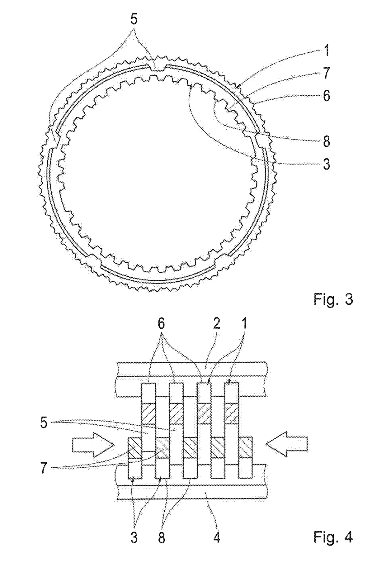
[0033]FIGS. 1 to 27 show various embodiments of the frictional shift element in accordance with exemplary aspects of the invention for a transmission of a motor vehicle, for example as a multi-disk shift element.

[0034]The frictional shift element includes multiple first frictional elements 1, which are mounted in a torque-proof manner on a first carrier 2 and multiple second frictional elements 3, which are rotatably mounted on a second carrier 4. The first and second frictional e...


PUM


Abstract

A frictional shift element for a motor vehicle transmission includes a first frictional element allocated to a first carrier; and a second frictional element allocated to a second carrier. One of the first frictional element or the second frictional element has an annular frictional surface, and the other of the first frictional element or the second frictional element has a corresponding frictional surface with at least one frictional surface that protrudes along a radial direction in an overlapping area.

Description

FIELD OF THE INVENTION[0001]The present invention relates to a frictional shift element for a transmission of a motor vehicle.BACKGROUND[0002]For example, a transmission with multiple frictional shift elements for the presentation of different transmission ratios is known from document DE 10 2009 001 101 A1. The frictional shift elements are formed as multi-disk shift elements, whereas the inner multi-disks and the outer multi-disks are designed with cover-free frictional surfaces, in order to increase the permissible surface pressure, such that the shift element has smaller dimensions with the same transfer capacity, and causes lower drag torques in the open mode.[0003]Furthermore, document DE 10 2009 027 017 A1 discloses a multi-disk pack for a multi-disk brake or a multi-disk clutch, with which a spring action is integrated into the multi-disks, such that a desired distancing between the multi-disks is also provided in the open state of the multi-disk pack. This results in a clea...

Claims


Application Information

Patent Timeline
IPC IPC(8): F16D13/52F16D13/64F16D13/69F16D13/68
CPCF16D13/52F16D13/69F16D13/683F16D13/648
Inventor REISCH, MATTHIASZIEMER, PETERBECK, STEFANSIBLA, CHRISTIAN
Owner ZF FRIEDRICHSHAFEN AG
Why Eureka
Try Eureka