Coalescing type filter apparatus and method

a filter apparatus and coalescing technology, applied in the direction of valve operating means/release devices, separation processes, etc., can solve the problems of high manufacturing cost of thick-walled filter housings and the small size of filter housings

Active Publication Date: 2008-02-05
IND TECH & SERVICES AMERICAS INC
View PDF15 Cites 44 Cited by
  • Summary
  • Abstract
  • Description
  • Claims
  • Application Information

AI Technical Summary

Problems solved by technology

Because of the large pressure differential that may exist between the interior and exterior of the filters, coalescing type filters are typically provided with a rather thick-walled filter housing that is costly to manufacture.
Because of limited available space, however, the filter housings are usually relatively small and as a result, frequent servicing of the filters is typically required to drain off coalesced liquids.
In many cases, the two chamber design of coalescing type filters results in the accumulation of liquid within each separate chamber and engineering challenges remain in removing accumulated liquid from either chamber without re-introducing the removed liquids back into the gas stream.

Method used


Image

  • Coalescing type filter apparatus and method
  • Coalescing type filter apparatus and method
  • Coalescing type filter apparatus and method

Examples


Embodiment Construction

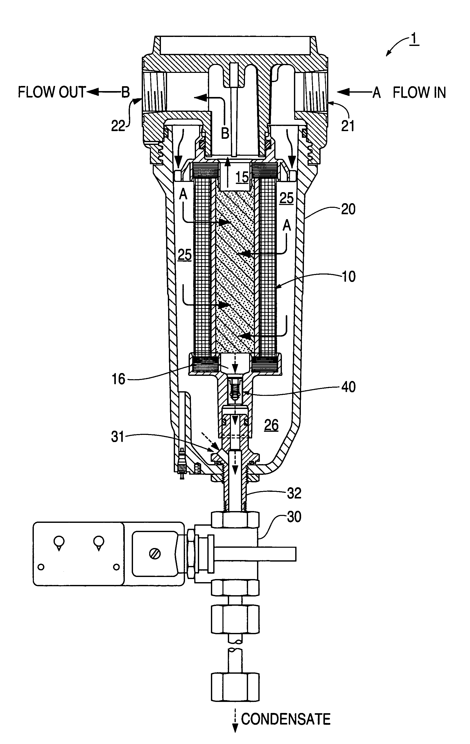
[0018]The invention will now be described with reference to the drawing figures, in which like reference numerals refer to like parts throughout. FIG. 1 shows a coalescing-type filter 1 in one embodiment of the present invention. It should be noted that coalescing filter structures and designs of the present invention can utilize a variety of forms including those of conventional coalescing filter structures, for example, discs, flat panels, and pleated or unpleated cylinders. They may also comprise simple or composite media.

[0019]Coalescing filters of the instant application may be used in applications to remove liquids, such as water or oil, from fluids, such as gas or air. The term oil includes at least petroleum based and synthetic hydrocarbons plus other synthetic oils such as di-esters which can affect materials such as acrylics in downstream equipment or processes.

[0020]As depicted in FIG. 1, a preferred filter 1 comprises a cylindrical filter element 10, housed within a cyli...


PUM

PropertyMeasurementUnit
pressureaaaaaaaaaa
pressureaaaaaaaaaa
pore sizeaaaaaaaaaa

Abstract

A coalescing type gas filter includes a filtering element enclosed in an inner chamber which is housed in an outer chamber and a drain device to simultaneously drain accumulated liquid in both the inner chamber and the outer chamber. The drain device contains a pressure sensitive valve that regulates opening of the drain in response to a drop in pressure.

Description

FIELD OF THE INVENTION[0001]The present invention relates generally to a filter arrangement and filtering method for use with a vessel containing a pressurized fluid. More particularly, the arrangement includes a coalescing filter assembly disposable inside a vessel.BACKGROUND OF THE INVENTION[0002]Coalescing filters are used in applications to remove liquids, such as water or oil, from fluids. Typically, such filters are located downstream of a vessel or cylinder containing the fluid, such as air or gas. Because of the large pressure differential that may exist between the interior and exterior of the filters, coalescing type filters are typically provided with a rather thick-walled filter housing that is costly to manufacture. Because of limited available space, however, the filter housings are usually relatively small and as a result, frequent servicing of the filters is typically required to drain off coalesced liquids.[0003]A coalescing type filter is designed to remove oil and...

Claims


Application Information

Patent Timeline
Patent Type & Authority Patents(United States)
IPC IPC(8): B01D46/10B01D46/00B01D46/24B01D46/52
CPCB01D46/0031B01D46/2411B01D46/521Y10S55/17B01D2201/295Y10T137/3105Y10T137/7782B01D46/0045
Inventor BARNWELL, JAMES W.
Owner IND TECH & SERVICES AMERICAS INC
Why Eureka
Try Eureka