Lighting fixture with smooth adjustable beam width

Inactive Publication Date: 2008-02-12
HAYMAN JEFFERY JOHN +1
View PDF7 Cites 34 Cited by
  • Summary
  • Abstract
  • Description
  • Claims
  • Application Information

AI Technical Summary

Benefits of technology

[0012]The invention herein described is for a fluorescent lighting fixture with a smooth transition adjustable lighting pattern. The lighting pattern can be adjusted from a wide to narrow illumination field. This adjustment is accomplished by two (2) screws, one on each end, to move the reflector away from the fluorescent lamps to widen the illumination field and toward the lamps to narrow the illumination field. Increments are printed on four (4) corners of the ballast chassis such that the installer can see and adjust to the exact pattern desired. Once the field width has been adjusted, the position is fixed by means of a locking device. Th

Problems solved by technology

That is, the lamps and reflector direct and concentrate the light to focus on a fixed area, thereby limiting the installation flexibility.
An additional issue is that existing lighting fixtures are frequently limited to static direct or indirect lighting, or a mixture of both.
A further issue is that the addition of more lamps to the fixture, to increase lighting intensity while maintaining high efficiency, cause

Method used


Image

  • Lighting fixture with smooth adjustable beam width
  • Lighting fixture with smooth adjustable beam width
  • Lighting fixture with smooth adjustable beam width

Examples


Embodiment Construction

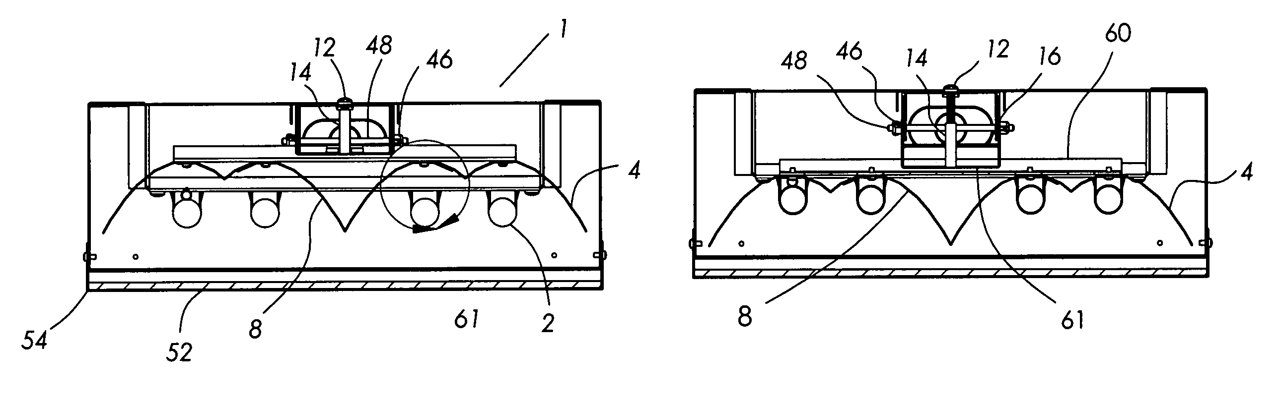
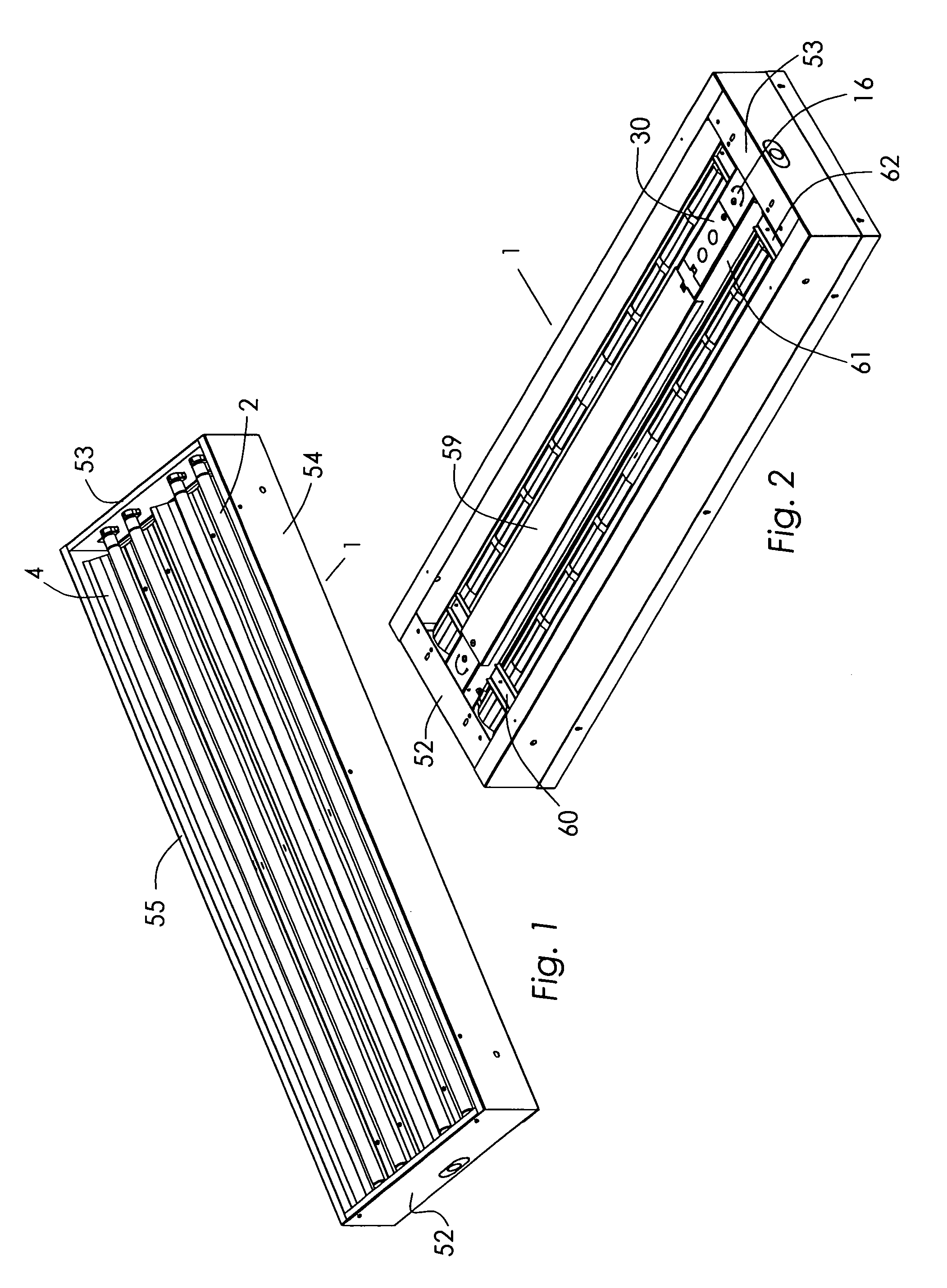
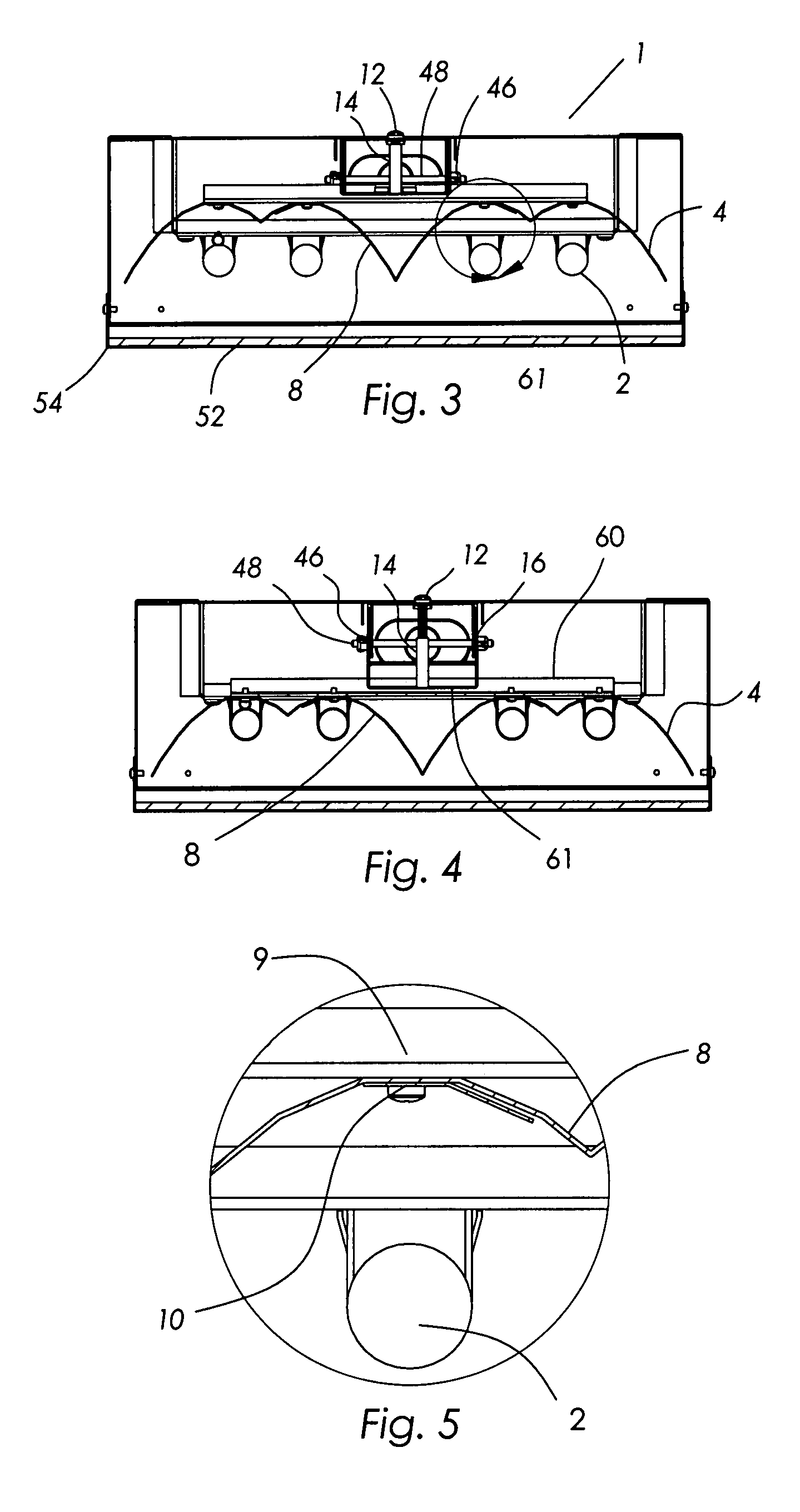
[0028]An overall view of the present invention is shown in FIGS. 1 and 2. FIG. 1 shows the lighting fixture 1 from the bottom, lamp side with the lens and lens mounting kit removed. FIG. 2 shows the lighting fixture from the top. The lamp fixture housing is formed from a pair of end caps 52 and 53 and a pair of side rails 54 and 55 to form the outside periphery of the lighting fixture 1. In FIG. 2, the static reflector-mounting strut 16 is rigidly affixed to the end caps 52 and 53. In the preferred embodiment, this rigid affixation is welded. It will be recognized that this rigid affixation may be accomplished by pop rivets, high strength tapes and adhesives and threaded fasteners. In addition, shown in FIG. 2 is the ballast cover 59, which covers the electronic ballasts, not shown, and provides access to the ballasts, housed in a ballast cavity, for installation and service. The ballasts are electrically connected to the lamps 2 and provide power suitable for starting and providing...


PUM


Abstract

A lighting fixture having a main housing to which is attached a moveable reflector assembly. The fluorescent lamps are affixed to the main housing and the moveable reflector assembly is adjusted to a position close to the fluorescent lamps to achieve a narrow illumination field. Adjusting the position of the moveable reflector assembly away from the fluorescent lamps achieves a wide illumination field. The reflector is designed as a near parabolic like shape and may be configured as a single fluorescent lamp cavity, or a multiple lamp cavity wherein the parabolic like shapes for each fluorescent lamp intersect to provide a uniform illumination light field and highly efficient light output while minimizing the lighting fixture width.

Description

CROSS-REFERENCES TO RELATED APPLICATIONS[0001]Not ApplicableSTATEMENT REGARDING FEDERALLY SPONSORED RESEARCH OR DEVELOPMENT[0002]Not ApplicableMICROFICHE APPENDIX[0003]Not ApplicableBACKGROUND OF THE INVENTION[0004]1. Field of the Invention[0005]The present invention pertains to the field of Lighting Fixtures and more particularly to a fluorescent lighting fixture having an adjustable beam pattern.[0006]2. Prior Art[0007]Most current fluorescent lighting fixtures have a fixed lighting pattern. That is, the lamps and reflector direct and concentrate the light to focus on a fixed area, thereby limiting the installation flexibility. The lighting fixtures create a situation wherein, in many cases, the application area either is over or under illuminated. The present invention resolves this limitation through providing a means to smoothly transition between a very wide to very narrow illumination distribution pattern.[0008]An additional issue is that existing lighting fixtures are freque...

Claims


Application Information

Patent Timeline
IPC IPC(8): F21S8/00F21V19/02F21V7/00
CPCF21S4/003F21S8/04F21S8/06F21V7/0016F21V7/005F21V11/12F21V11/18F21V14/04F21V14/08F21V17/02F21Y2103/00F21Y2113/00F21V21/005F21S4/20
Inventor HAYMAN, JEFFERY JOHNMACGILVRAY, JEREMY JOSEPH
Owner HAYMAN JEFFERY JOHN
Why Eureka
Try Eureka