Film unwind system with hinged spindle and electronic control of web tension

a technology of electronic control and unwinding system, which is applied in the direction of transportation and packaging, thin material processing, filament handling, etc., can solve the problem that the film roll cannot fit onto the spindle, and achieve the effect of maintaining a tension sta

Inactive Publication Date: 2008-02-19
PREGIS INTELLIPACK CORP
View PDF52 Cites 32 Cited by
  • Summary
  • Abstract
  • Description
  • Claims
  • Application Information

AI Technical Summary

Problems solved by technology

If an operator tries to slide the roll on the wrong way, (i.e., with the “roll support, small end” as the leading end), the film roll will not fit onto the spindle as the inside diameter of the “roll support, small end” core plug is not sufficient to clear the larger diameter of the spindle mounting surface closest to the spline drive.

Method used


Image

  • Film unwind system with hinged spindle and electronic control of web tension
  • Film unwind system with hinged spindle and electronic control of web tension
  • Film unwind system with hinged spindle and electronic control of web tension

Examples


first embodiment

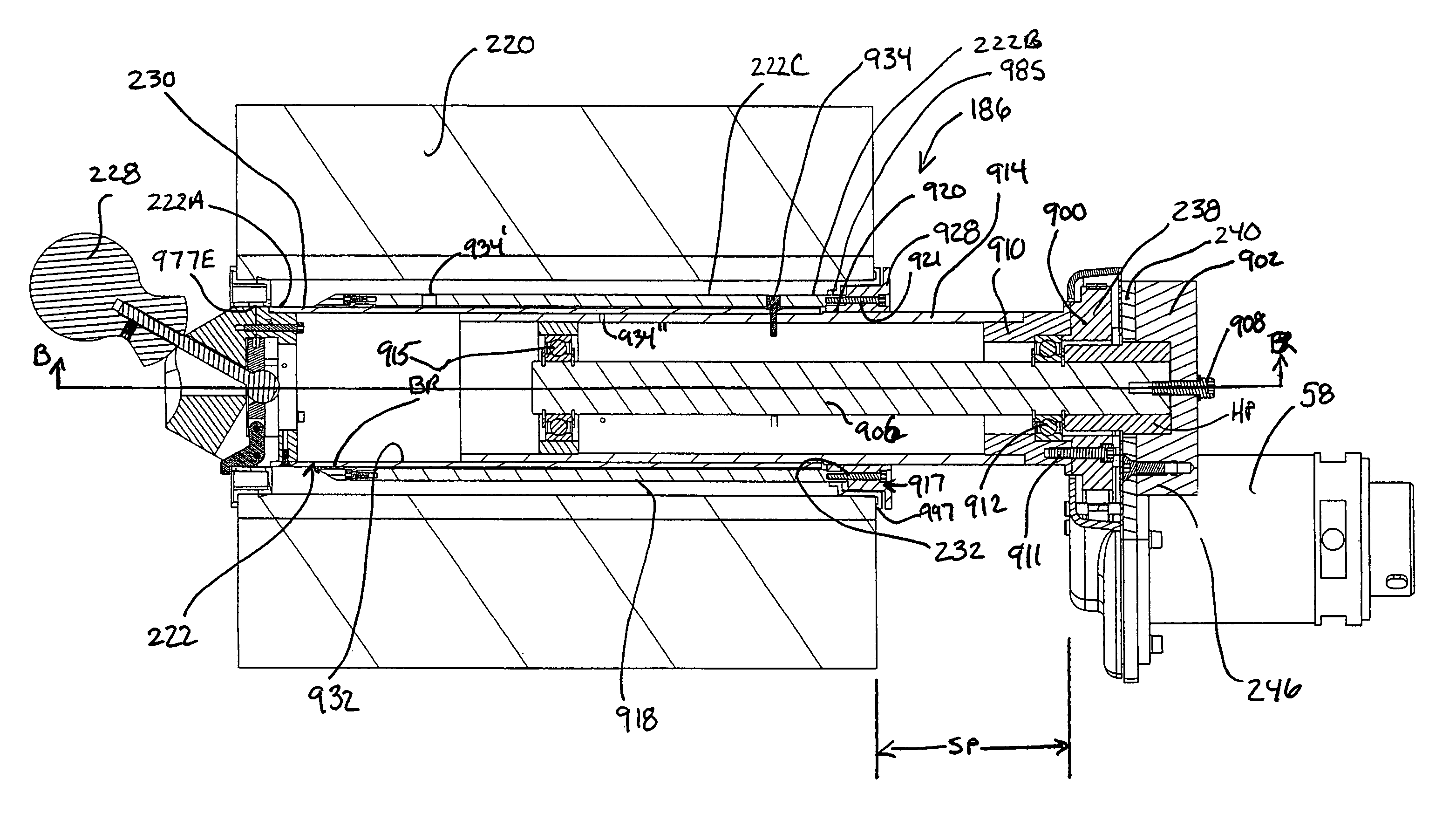
[0289]sealer shifting assembly 120 is shown in FIGS. 9, and 9A to 9E and comprises first and second sealer support rod assemblies 122, 124 each having a front a forward end with reception blocks 121, 123 having a recess area securement means for receiving and securing jaw 118. The securement means is preferably in the form of an elongated (end threaded) rod, 126 (FIG. 9E) extending through a respective one of blocks 121, 123 and into threaded engagement with a respective jaw extension 141, 143 laterally external to the main or contact body of jaw 118. The supported rod assemblies 122, 124 are preferably designed the same, but for their mirror image orientation. Rod 126 has a rear end extending through cylinder extensions 147 (FIG. 9B) and out through block 125 and out the rear of block 125 and having blocking member 117 (e.g., threaded cup). Rod 126 is surrounded by cylindrical sleeve SL extending between cap 117 and jaw extension 143. Spring 130 surrounds sleeve SL and extends into...

second embodiment

[0293]FIG. 9F shows a perspective view of a moving jaw assembly 4000 which retracts and pushes forward jaw block 118 against the preferably stationary jaw 116 with heated cross cut and seal wires. The rear end of block 118 is connected at opposite ends to respective casings 4002 and 4004 with these casings forming a part of the cam force transmission devices 4006 and 4008. Cam force transmission devices 4006 and 4008 are the same except for their mirror image positioning (and below described home positioner) and thus the discussion focuses on transmission device 4006 alone. Casing 4004 is secured to frame structure 66 of bagger assembly 64 at its expanded ends and has an interior reception chamber formed along its inner side. As seen from FIG. 91, within this chamber is positioned bearing plates 4010 and 4012 which receive in sliding fashion cam rod 4014. The rear end of cam rod 4014 includes cam yoke 4015 which supports cam roller 4016 which rides along cam 4018 having a eccentric ...


PUM

PropertyMeasurementUnit
volumeaaaaaaaaaa
angleaaaaaaaaaa
lengthaaaaaaaaaa

Abstract

A film supply apparatus supplying film in a foam-in-bag system having a film feeding device for feeding film from a film source to a location for bag formation, a bag forming apparatus, a foam material dispenser positioned for feeding foam material for reception in a bag of the bag forming apparatus, and a web tensioning system with a web tensioning driver in driving communication with the film source and which is in communication with a controller for monitoring the film feed and web tension states and directing adjustments in the web tension system. The web tensioning driver is arranged to move film backwards or in a direction opposite to a direction of film feed induced by the film feeding means and with the film source including a roll of film and the web tensioning system including a drive transmission in communication with the roll of film for rotational driving of the roll of film and also in communication with web tensioning driver. There is further featured a spindle support for supporting the roll of film and a roll film core drive insert.

Description

CROSS REFERENCE TO RELATED APPLICATIONS[0001]Priority under 35 U.S.C. § 119(e) is claimed relative to the Provisional Patent Application referenced as “G” in the Table immediately below, which was filed on May 9, 2003. The disclosure of each of the 15 provisional applications A to O set forth below is incorporated herein by reference.[0002]TABLE 1REF.ID.Ser. No.FILEDTITLEA60 / 468,942May 9, 2003Dispenser Assembly WithMixing Module DesignB60 / 469,034May 9, 2003Bagger With Integrated,Inline Chemical PumpsC60 / 469,035May 9, 2003Mixing Module Drive MechanismD60 / 469,037May 9, 2003Mixing Module Mounting MethodE60 / 469,038May 9, 2003Dispenser Tip Management SystemF60 / 469,039May 9, 2003Hinged Front Access Panel ForBag Module Of, For Example, AFoam In Bag DispenserG60 / 469,040May 9, 2003Improved Film Unwind SystemWith Hinged Spindle AndElectronic Control Of WebTensionH60 / 469,042May 9, 2003Exterior Configuration Of AFoam-In-Bag Dispenser AssemblyI60 / 468,988May 9, 2003Bag Forming System Edge SealJ60...

Claims


Application Information

Patent Timeline
Patent Type & Authority Patents(United States)
IPC IPC(8): B65H16/04B29C44/18B65H19/10B65H19/12
CPCB65H19/10B29C44/18B65H2301/413226B65H2405/422B65H2405/45B65H2407/20
Inventor COCCIADIFERRO, EDWARDNOBLE, LYNN
Owner PREGIS INTELLIPACK CORP
Why Eureka
Try Eureka