

Abdominal bench with constant gap torso cushion
a technology of abdominal bench and cushion, which is applied in the field of abdominal bench, can solve the problems of reducing the effectiveness of abdominal exercise and reducing the effectiveness of exercis
- Summary
- Abstract
- Description
- Claims
- Application Information
AI Technical Summary
Benefits of technology
Problems solved by technology
Method used
Image

Examples
Embodiment Construction
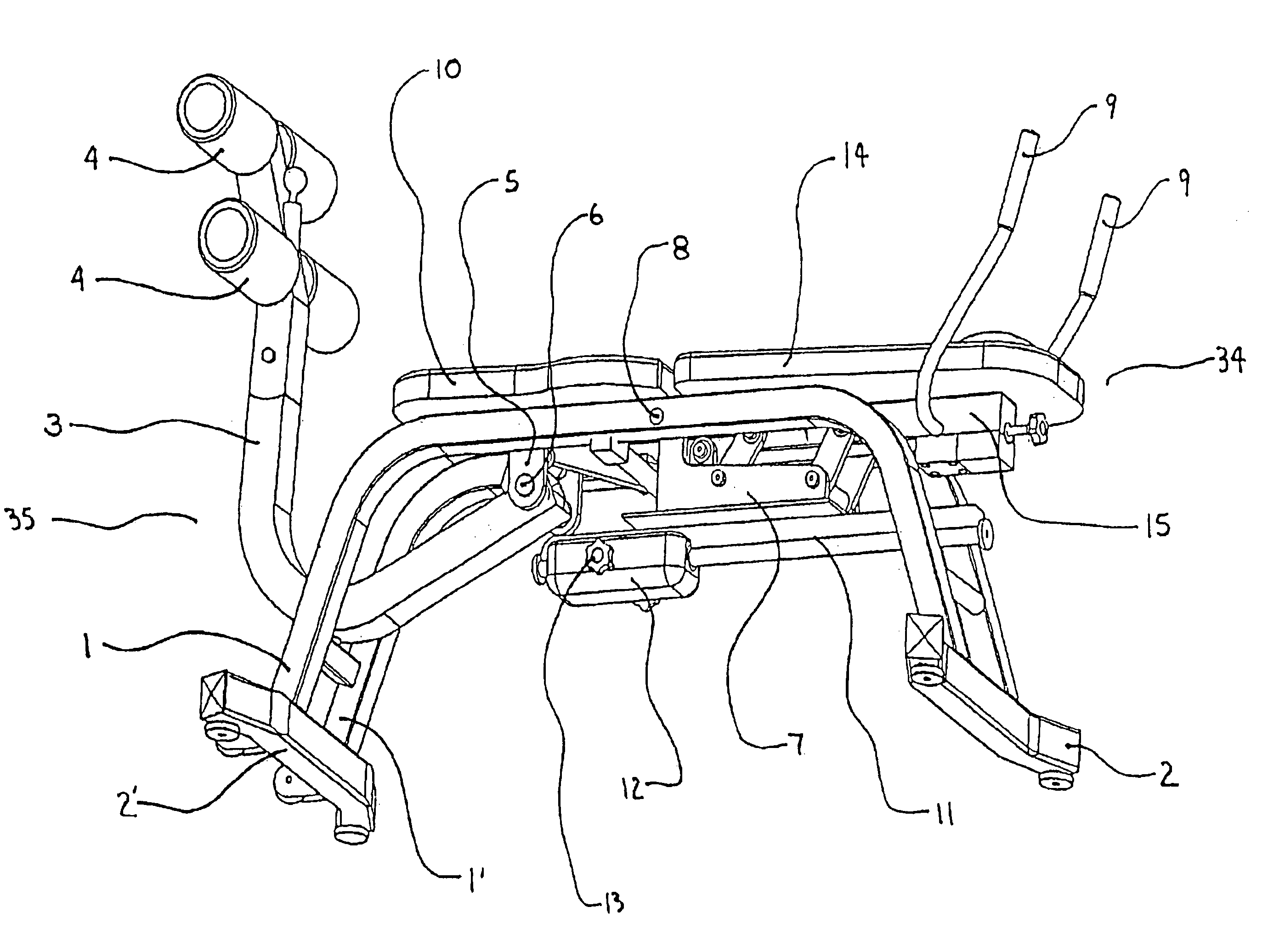
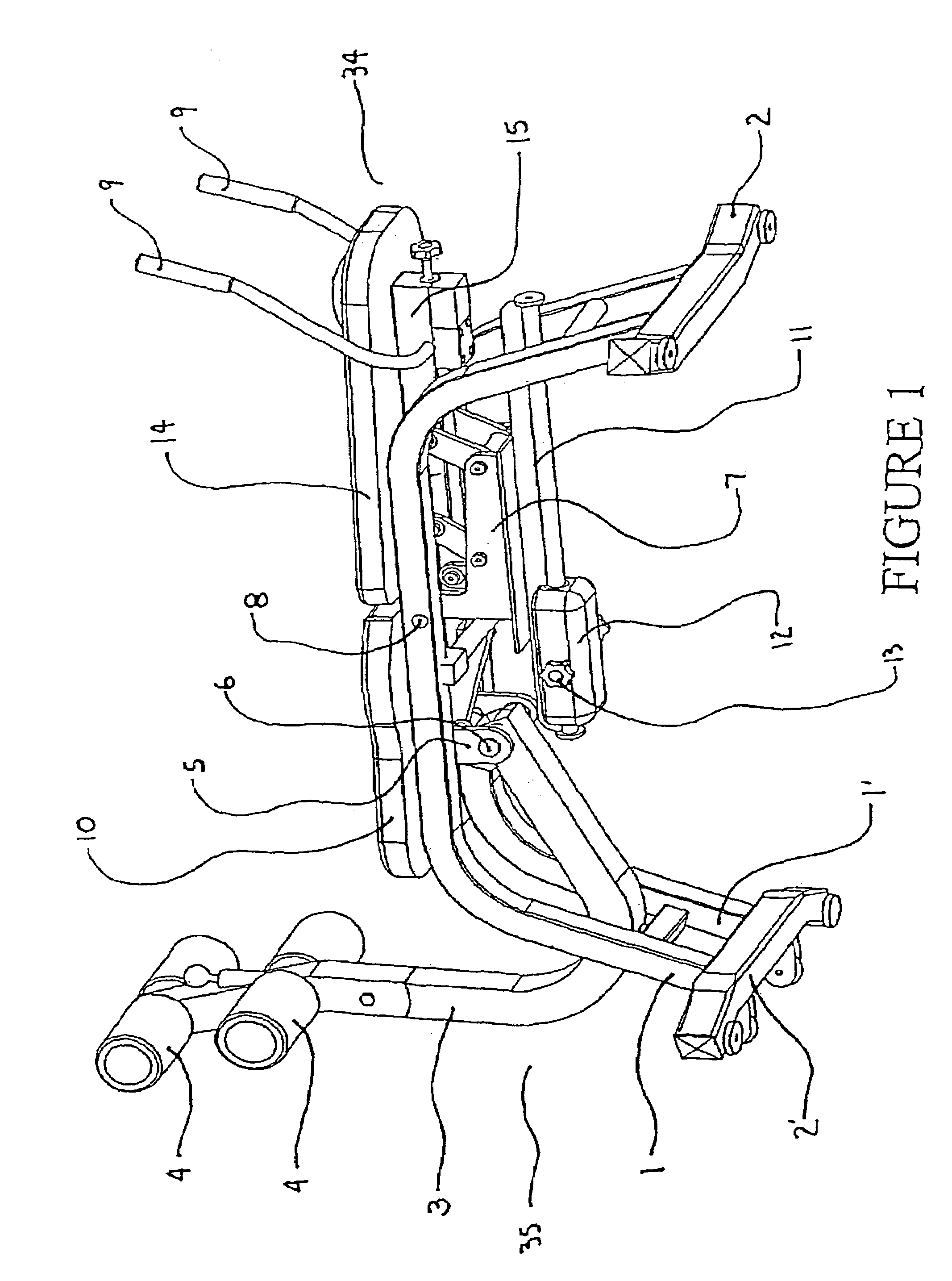
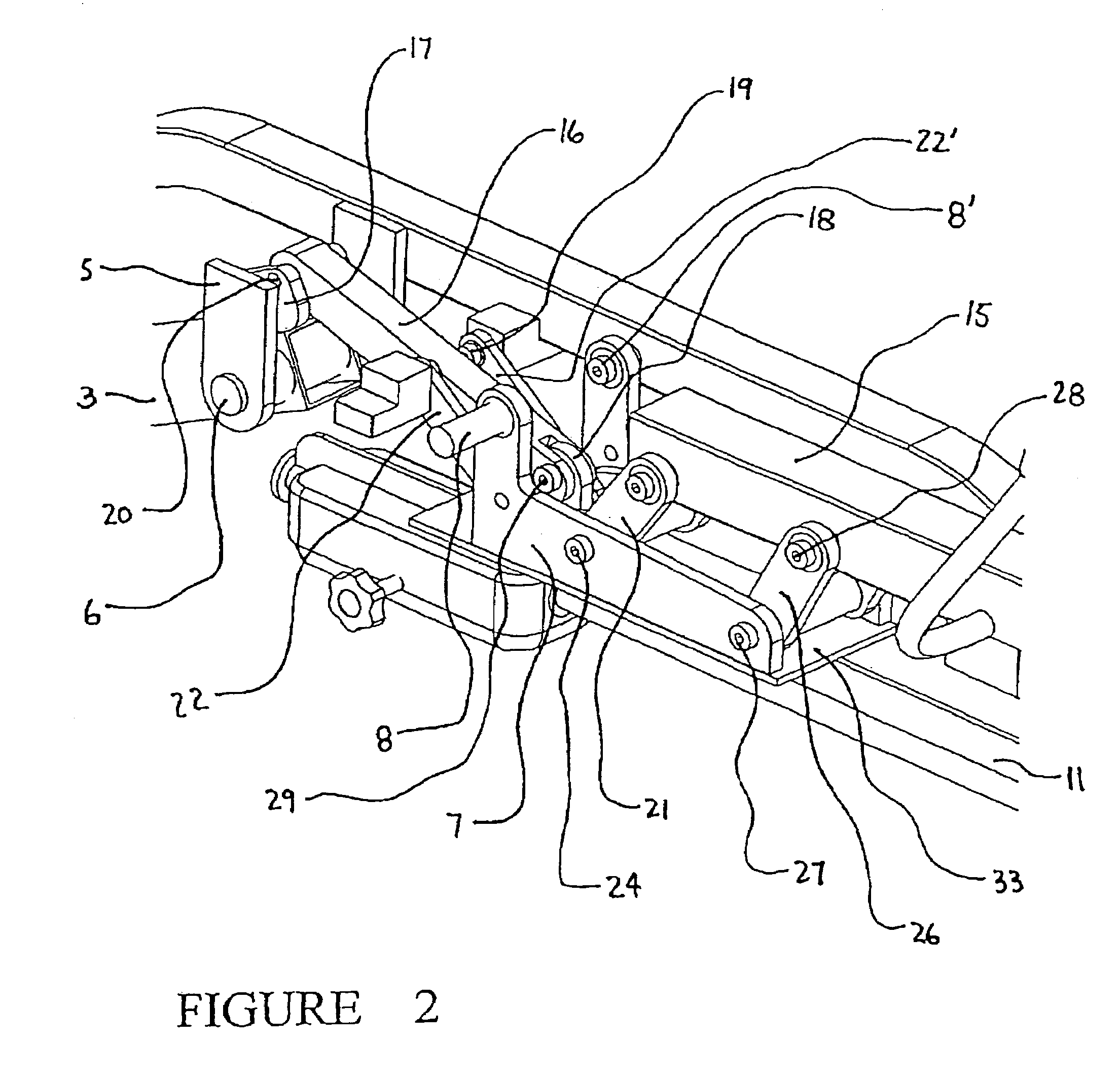
[0010]A pivoting abdominal bench has a fixed seat section and a pivoting upper torso section. The bench also has a pivoting leg and footrest section. The lower end of the leg and, footrest section is connected to a push rod. The push rod is connected to the lower end of the pivoting torso section. At least one guide rod is pivotably connected between the frame and a dog-leg lever. The dog-leg lever is pivotably connected to the lower part of the torso section. The arrangement of the rods, levers and pivots allows the exerciser to pivot the upper torso section upward while pivoting the leg and feet inwardly toward the abdomen. Due to the unique pivot system and the connection of the foot and leg rest to the torso section through the push rod, the torso section remains a constant distance from the seat section during the exercise. The constant gap between the pivoting torso section and the fixed seat section eliminates any pressure on the lower portion of the body that could result fr...
PUM
 Abstract
Description
Claims
Application Information