Computer interface device

Inactive Publication Date: 2008-02-19
GARD MATTHEW DAVIS
View PDF21 Cites 10 Cited by
  • Summary
  • Abstract
  • Description
  • Claims
  • Application Information

AI Technical Summary

Benefits of technology

[0012]In a broader application, a panel sensor can be placed on the wall of a room. The location of a user within the room can be detected. Multiple panels can be linked together to establish greater sensitiv

Problems solved by technology

A common problem is the accumulation of lint, carried by the roller ball and lodged against the sensor.
This prevents the sensor from properly recording the movement of the roller ball.
Further, the ball can become irregular with time, making it more difficult to roll.
Another problem occurs when the mouse is placed upon a smooth sur

Method used


Image

  • Computer interface device
  • Computer interface device
  • Computer interface device

Examples


Example

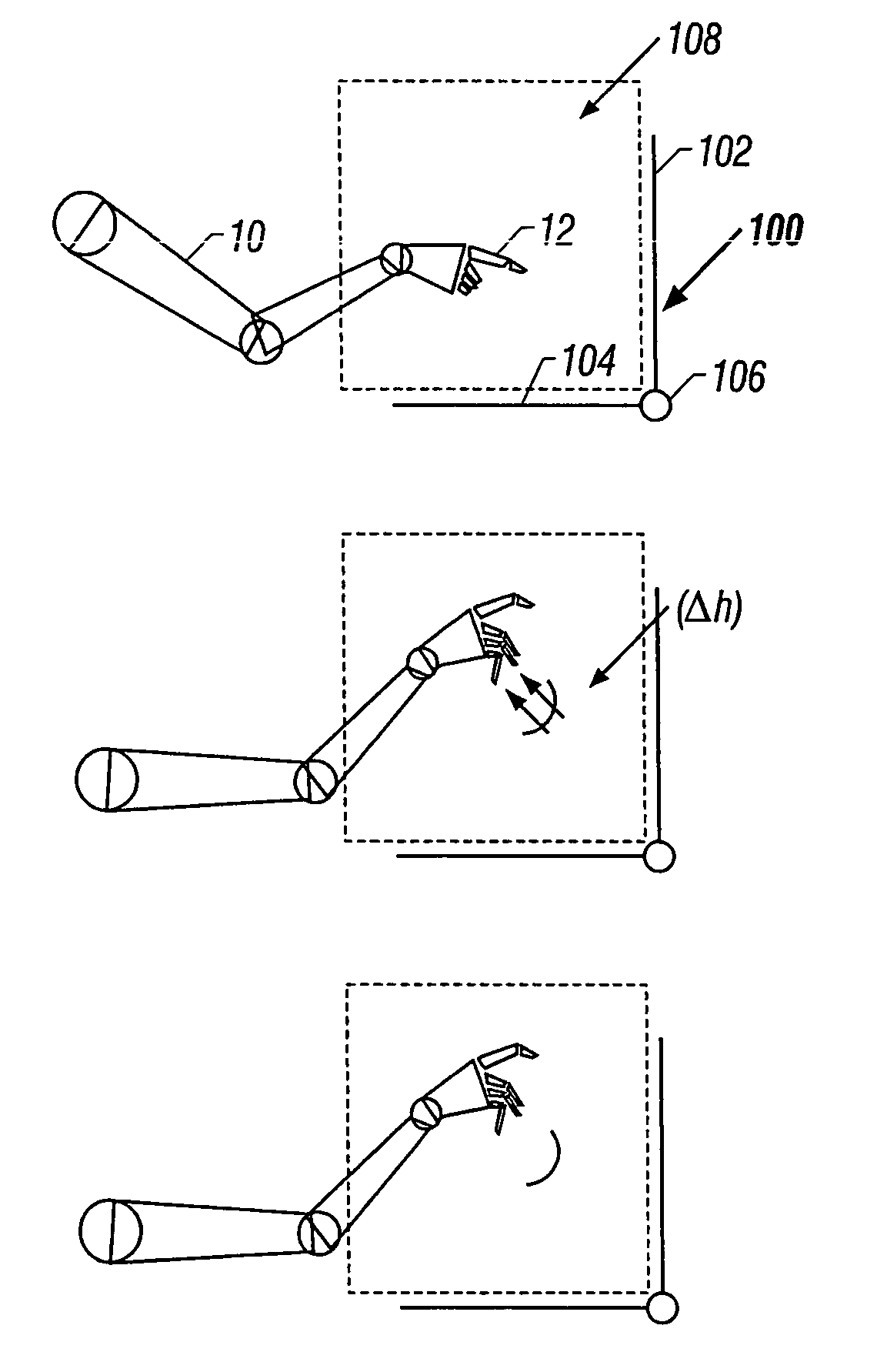
[0026]The present invention relates to a computer interface device and more generically to a control device which senses a user's movements to initiate control actions. FIG. 1 provides a general illustration of a user 10 gesturing within a field established by a first, second, and third conductors 102, 104, and 106. The third conductor 106 is extending from the page in the z-axis. The conductors establish a capacitance with the air acting as a dielectric. The dielectric constant is disturbed by the presence of the user's hand or other extremity. Alternatively, the user's hand or other extremity forms the second plats of the capacitor along with the conductor. Movement of the user then alters the capacitance of this capacitor as the body provides a virtual ground to close the circuit. For example, the movement of the user's finger 12 in the upward direction as shown in the second frame creates a disturbance or “bounce effect.” A detector circuit will sense this change, for example, a...


PUM


Abstract

A user's movements are detected by a capacitive system having one or more conductors. The output from the conductors is amplified and compared to a table of stored output. Thus, the device can eliminate the need to touch a control surface. The control surface such as a computer mouse could be eliminated in favor of merely sensing a user's hand movement. Likewise, the array of conductors could be placed in a panel that could be mounted on a wall. Such panels could be used in a factory to sense the movement of workers or a machinery. Indeed, the movements could be analyzed and warnings sounded if a collision is predicted.

Description

[0001]This application is a continuation of application Ser. No. 08 / 778,978, filed Jan. 6, 1997, now U.S. Pat. No. 5,990,865, which is incorporated by reference for all purposes into this application.BACKGROUND OF THE INVENTION[0002]1. Field of the Invention[0003]The present invention relates to a computer interface device for controlling the position of a cursor on a computer monitor. More generally, the device can be used to detect a user's position and translate this position into a distinguishable input for a computer.[0004]2. Description of the Related Art[0005]Most computers today use a “mouse” to control the location of a cursor on the screen. It is important to be able to quickly and accurately position the cursor, especially when working with programs having a graphical user interface. The mouse is a simple device which uses a roller ball. As the mouse is moved, the roller ball moves two perpendicular sensors. One sensor detects movement towards or away from the user. The o...

Claims


Application Information

Patent Timeline
IPC IPC(8): G09G5/08G06F3/00G06F3/01G06F3/033G06F3/044G06K9/00
CPCG06F3/011G06F3/0346G06F3/044G06K9/00335G06F2203/04101G06V40/20
Inventor GARD, MATTHEW DAVIS
Owner GARD MATTHEW DAVIS
Why Eureka
Try Eureka