
Camera-linked surveillance system

a camera and surveillance technology, applied in the field of surveillance systems, can solve the problem that the detection of an intruder's object with a single wide angle shooting camera is inevitably susceptible to a blind spo

Active Publication Date: 2008-02-26
PANASONIC CORP
View PDF6 Cites 31 Cited by
  • Summary
  • Abstract
  • Description
  • Claims
  • Application Information

AI Technical Summary

Benefits of technology

[0013]This provides an advantage that an intruding object can be kept track of with no blind spot with the minimum number of cameras by switching the role of detecting the object of monitoring from one camera to another according to the predetermined direction of the object of monitoring.
[0032]A similar advantage can also be realized by providing means which can recognize the direction of the intruding object and determines the function of each camera according to that direction.

Problems solved by technology

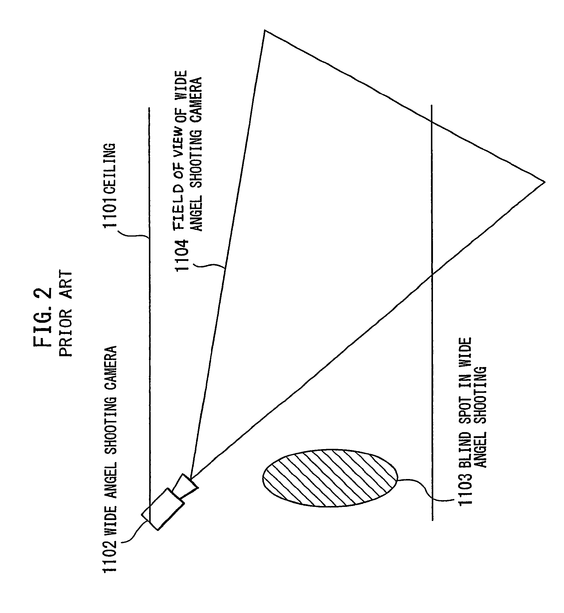
However, whereas two cameras are used according to the above-cited example of the prior art, detection of an intruding object with a single wide angle shooting camera is inevitably susceptible to a blind spot, near the position in which the wide angle shooting camera is installed, in which the intruding object cannot be detected.

Method used


Image

  • Camera-linked surveillance system
  • Camera-linked surveillance system
  • Camera-linked surveillance system

Examples


embodiment 1

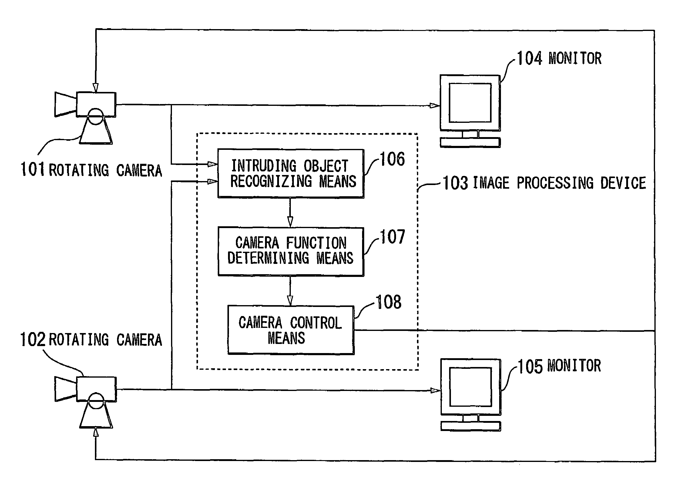
[0049]FIG. 3 through FIG. 11 illustrate a first preferred embodiment of the invention. Regarding this embodiment, it will be described how universal heads supporting cameras pan and tilt, and how two rotating cameras whose lenses can be zoomed in and out are used to keep track of any intruder and display his or her enlarged image on a screen.

[0050]FIG. 3 is a block diagram of the configuration of a surveillance system, which embodies the invention in this mode. This surveillance system comprises two rotating cameras 101 and 102 controllable for panning, tilting and zooming in and out with control signals, an image processing device 103 for processing image signals sent from the rotating cameras 101 and 102 and generating control signals for the rotating cameras 101 and 102 according to the result processing, and monitors 104 and 105 for displaying image signals sent from the rotating cameras 101 and 102 on their screens.

[0051]It is possible to allocate to each of the rotating camera...

embodiment 2

[0078]FIG. 12 is a block diagram of the configuration of a surveillance system, which is a second preferred embodiment of the invention. In FIG. 12, the same constituent elements as in FIG. 3 will be denoted by respectively the same reference signs, and their description dispensed with. A characteristic feature of this embodiment consists in that photographic monitoring, the function control it and a facial image recognizing device as image recognizing means are combined with one another and, by allocating a function to each rotating camera according to the result of recognition, the camera function can be switched in a way suitable for facial image recognition and the performance of facial image recognition is thereby improved.

[0079]In FIG. 12, reference numeral 1201 denotes a facial image recognizing device for recognizing the image of a human face as image recognizing means, and this device comprises facial image recognizing means 1202 for singling out a specific face out of faci...


PUM


Abstract

The surveillance system is configured of multi-camera including rotating cameras controllable for panning, tilting and zooming in and out, intruding object recognizing means for processing image signals from the rotating cameras and keeping track of a position of the intruding object, camera function determining means for allocating a tracking function to a first camera whose field of view is in a predetermined direction of the object of monitoring according to a state of the object of monitoring and allocating a wide angle shooting function for shooting a monitored space in a wide angle to a second camera, and camera control means for controlling the multi-camera according to actions of the camera function determining means.

Description

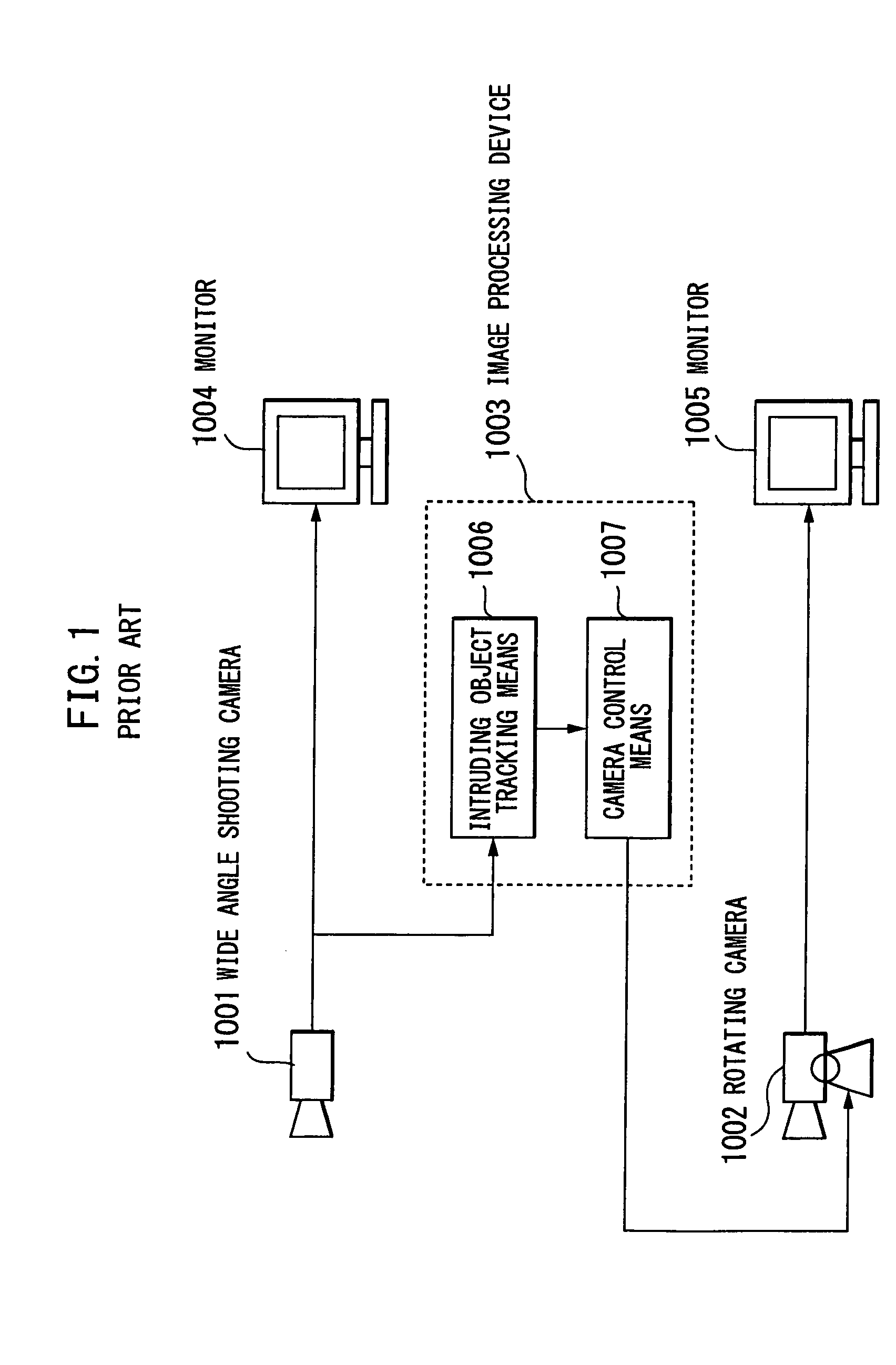
BACKGROUND OF THE INVENTION[0001]1. Field of the Invention[0002]The present invention relates to a surveillance system for automatically detecting an intruding object by using multi surveillance cameras and an image processing device, and displaying its enlarged image on a screen.[0003]2. Description of Prior Art[0004]In the field of surveillance equipment in recent years, there have emerged systems which not only display on a screen video signals supplied from cameras but also identify the position of any abnormality that has occurred by analyzing the signals with an image processing device, and presenting images of vicinities of the abnormality to the monitoring personnel.[0005]An example of such prior art is described in the Japanese Patent Disclosure No. 69342 / 1999 (Patent Reference 1). The Patent Reference 1 discloses an intruding object tracking image processing system which, in order to detect an intruding object, uses a camera having a wide angle lens and displays an enlarge...

Claims


Application Information

Patent Timeline
Patent Type & Authority Patents(United States)
IPC IPC(8): H04N7/18
CPCG08B13/19608G08B13/19628G08B13/1963G08B13/19641G08B13/19695H04N7/181
Inventor ISHIGAMI, TOMOHIDEMARUYA, KENSUKEOKADA, SUSUMU
Owner PANASONIC CORP
Learn More