Methods and apparatus for flow control based packet aggregation in a communication network

a communication network and flow control technology, applied in data switching networks, frequency-division multiplexing, instruments, etc., can solve problems such as inability to have enough rlp frames, increase packet delay, and degrade performance, and achieve the effect of improving transport efficiency

Inactive Publication Date: 2008-02-26
LUCENT TECH INC
View PDF7 Cites 13 Cited by
  • Summary
  • Abstract
  • Description
  • Claims
  • Application Information

AI Technical Summary

Problems solved by technology

It is not always possible, however, to have enough RLP frames to generate a large IP packet sent to the cell.
Blindly implementing such a scheme, however, will increase the packet delay and degrade performance.

Method used


Image

  • Methods and apparatus for flow control based packet aggregation in a communication network
  • Methods and apparatus for flow control based packet aggregation in a communication network
  • Methods and apparatus for flow control based packet aggregation in a communication network

Examples


Embodiment Construction

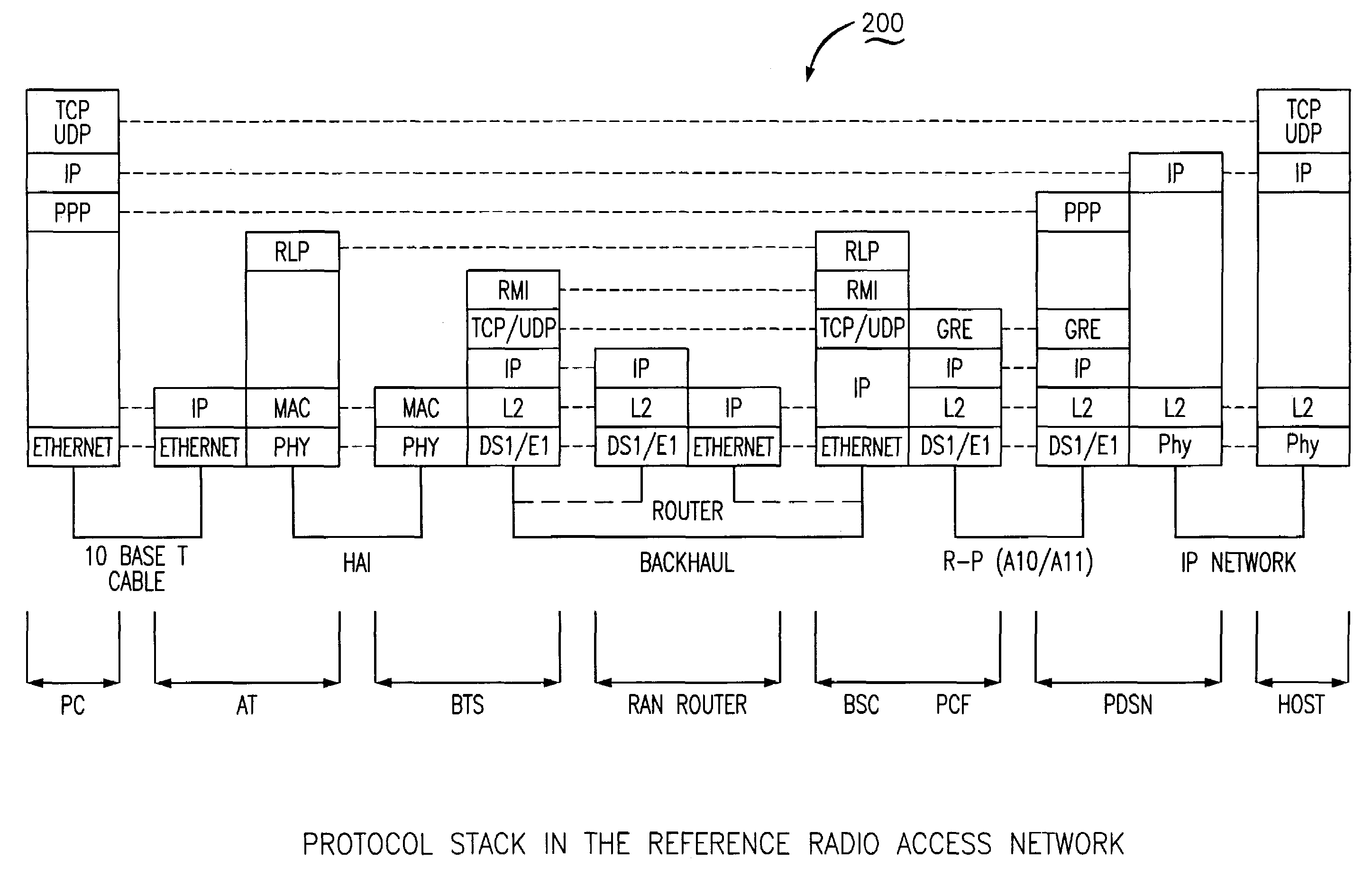
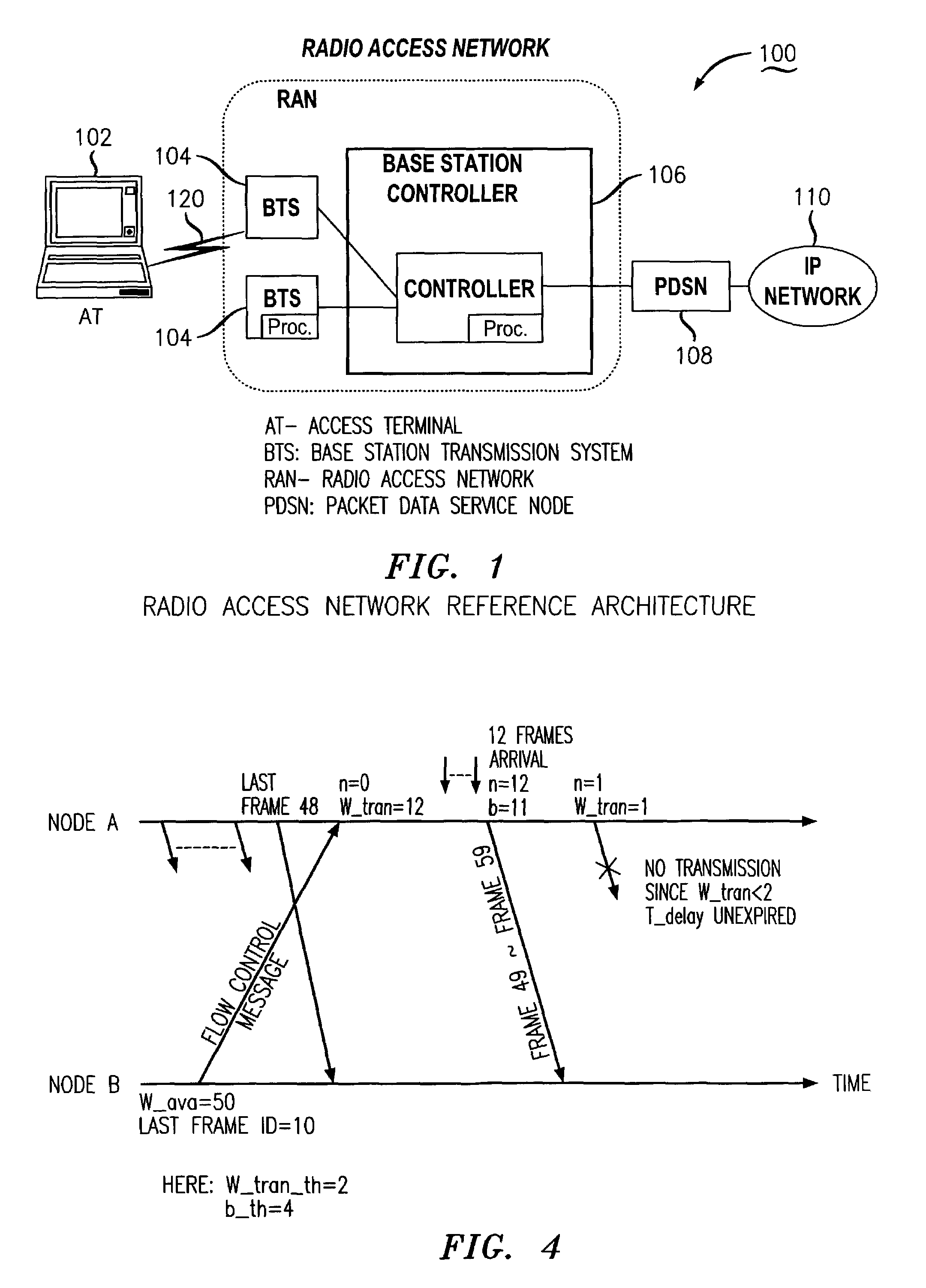
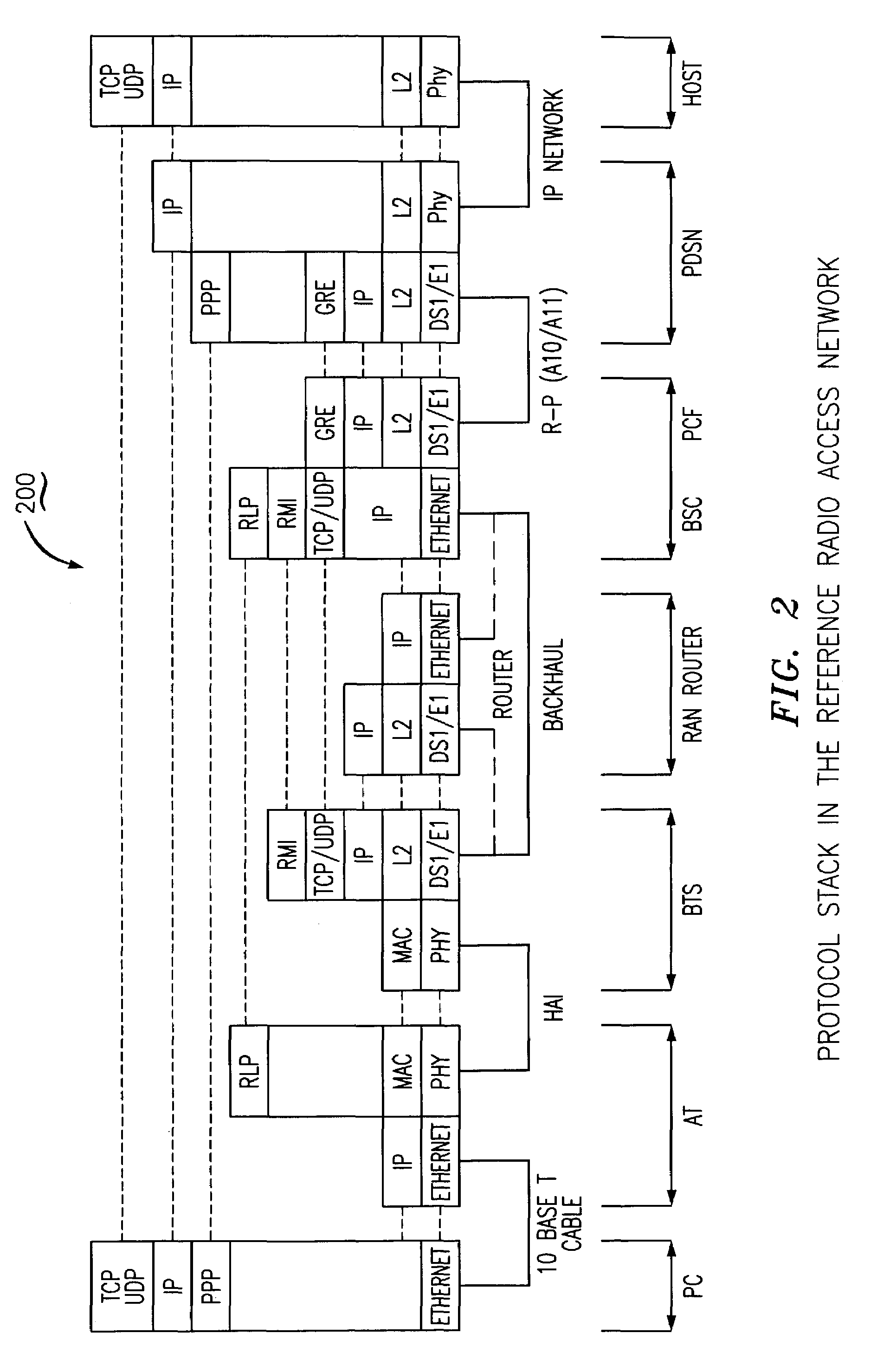
[0015]The present invention is a methodology for providing packet aggregation based on transmission window size to achieve improved transport efficiency. Although an exemplary embodiment of the invention is described in connection with the transmission between a base station controller (BSC) and a base station (BTS), and the interface / link between them, it would be apparent to those skilled in the art that the present invention is applicable to other network areas requiring packet aggregation, including, for example, voice over IP networks where small application layer packets (e.g., voice frames) need to be aggregated or multiplexed together to be transported over IP networks.

[0016]Referring to FIG. 1, an exemplary flow control mechanism is described with respect to a packet communications transmission between BSC 106 and BTS 104 (referred to hereinafter as Node A and Node B, respectively) for example from BSC to BTS. In accordance with the exemplary mechanism, the transmission win...


PUM


Abstract

The present invention is a methodology for providing packet aggregation based on transmission window size to achieve improved transport efficiency. One embodiment of the invention includes the steps of receiving an indication of a transmission window size for packets to be transmitted from a first location to a second location where the transmission window size provided by a flow control message. The transmission window size is utilized to determine a bundling factor for transmission of packets from said first location to said second location, the bundling factor being a lesser of a maximum bundling factor and the transmission window size. A transmission window size threshold represents a boundary for a size of a transmission window when transmission of existing frames may be delayed. The frames are bundled according to the bundling factor if the transmission window size is greater than the transmission window size threshold.

Description

FIELD OF THE INVENTION[0001]The present invention relates generally to packet communications networks and more particularly to packet aggregation and / or multiplexing techniques within such networks.BACKGROUND OF THE INVENTION[0002]Referring to FIG. 1, an exemplary network 100 including multiple nodes is shown. The exemplary network 100 may be, for example, a radio access network for high speed wireless data applications. Typical radio access networks, like that shown in FIG. 1 include one or more Access Terminals 102 (AT), Base Stations 104 (BTS), and Base Station Controllers 106 (BSC). A PDSN 108 interfaces between the IP network and the radio access network. The BSC 106 receives data from the core network 110 and passes the data to the BTS 104 so that the BTS can transmit the data to the AT 102 over the wireless link 120. Data is communicated through the reverse direction as well and passed from AT 102 to the core network 110. In general, each node consists of multiple functional ...

Claims


Application Information

Patent Timeline
Patent Type & Authority Patents(United States)
IPC IPC(8): H04J1/16H04J3/18H04L12/66H04Q7/00H04L12/56H04J3/24H04L12/28H04B7/216
CPCH04L12/5602
Inventor SAMADI, BEHROKHZHANG, QINQING
Owner LUCENT TECH INC
Why Eureka
Try Eureka