Hybrid compressor

a compressor and hybrid technology, applied in the direction of positive displacement liquid engines, piston pumps, liquid fuel engines, etc., can solve the problems of mechanical damage, current leakage, and damage to both compression mechanisms, so as to reduce or avoid mechanical and electrical damage, reduce or avoid damage to the second compression mechanism, and reduce or avoid current leakage

Inactive Publication Date: 2008-03-04
HONDA MOTOR CO LTD +1
View PDF33 Cites 1 Cited by
  • Summary
  • Abstract
  • Description
  • Claims
  • Application Information

AI Technical Summary

Benefits of technology

[0008]Thus, a need has arisen for a hybrid compressor, which may reduce or avoid mechanical and electrical damage, due to front end accident. Accordingly, it is an object to provide a structure for a hybrid compressor having a first compression mechanism driven by a first drive source and a second compression mechanism driven

Problems solved by technology

When an impact force is applied to the front end of the vehicle in an accident or the like, the same-degree of force may be applied to each of the first and second compression mechanisms, and both compression mechanisms may be damaged similarly.
However, be

Method used


Image

  • Hybrid compressor
  • Hybrid compressor
  • Hybrid compressor

Examples


Embodiment Construction

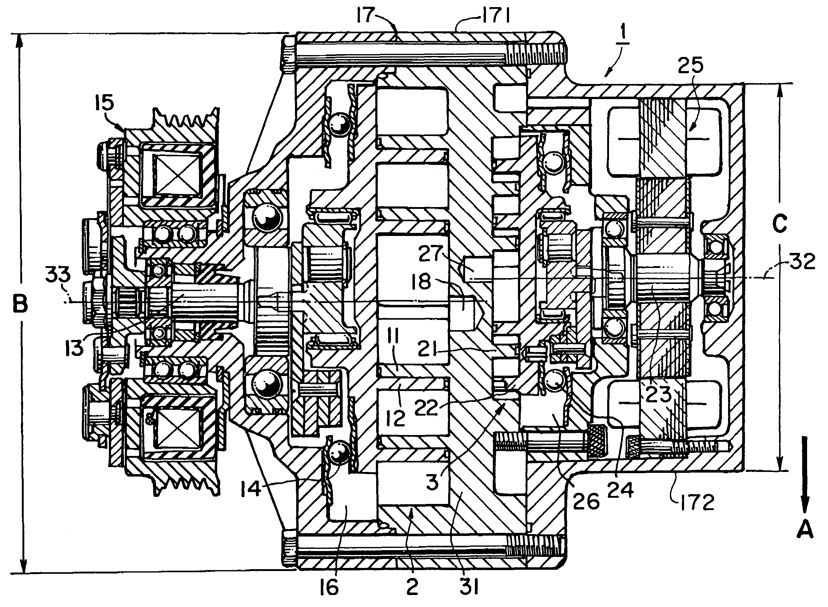
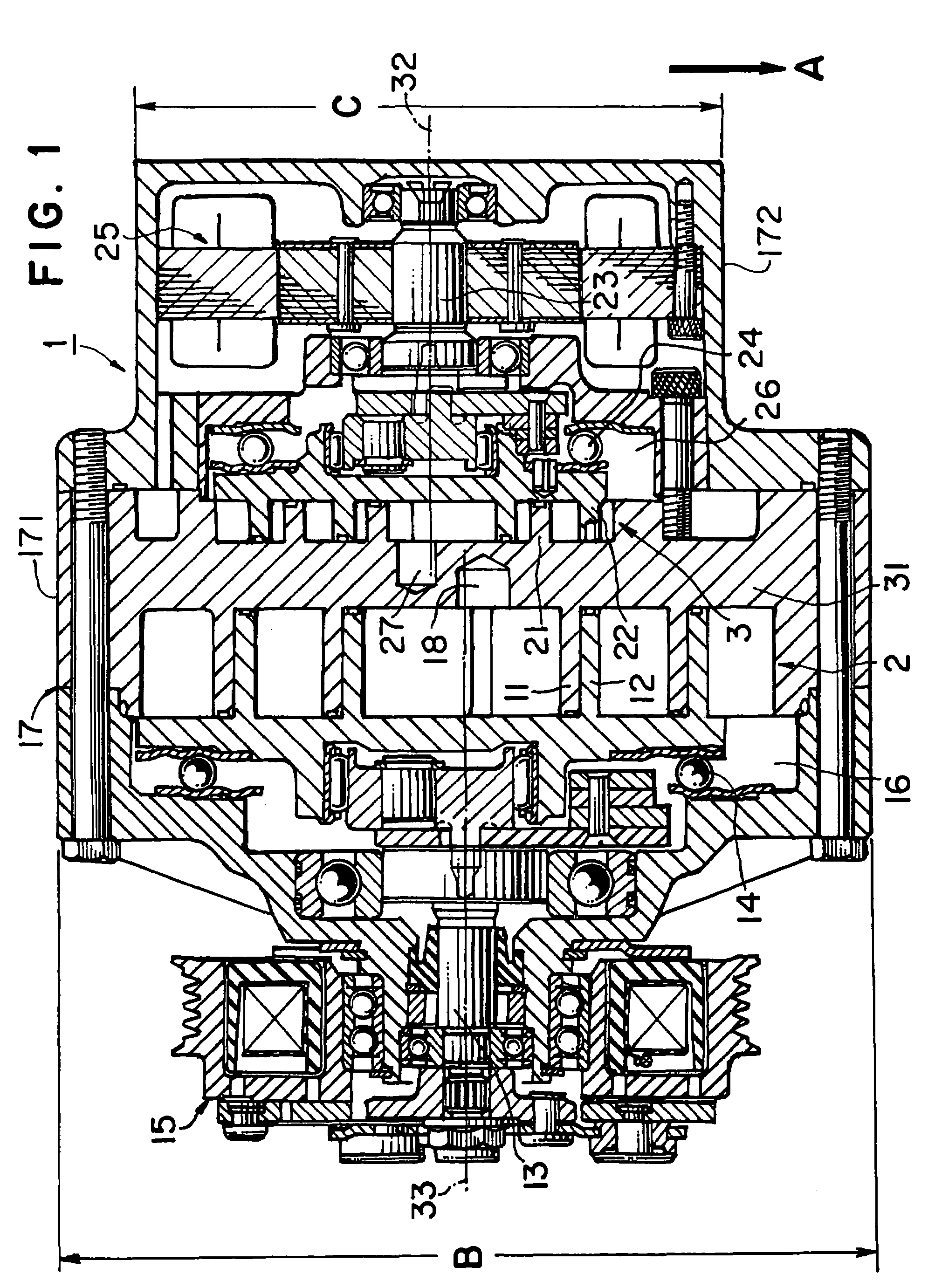
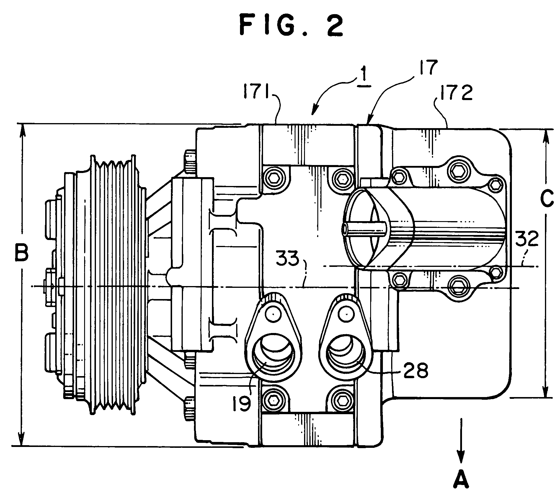
[0025]FIGS. 1 and 2 depict a hybrid compressor according to an embodiment of the present invention. This embodiment is shown as a preferred embodiment, in which the aforementioned configurations of the first and second hybrid compressors according to the present invention, are both employed. This hybrid compressor is used, for example, in a refrigerant cycle of an air conditioning system mounted on a vehicle.

[0026]In FIG. 1, hybrid compressor 1 comprises a first compression mechanism 2 driven exclusively by a first drive source (not shown) via an electromagnetic clutch 15 and a second compression mechanism 3 driven exclusively by an incorporated electric motor 25 provided as a second drive source. First and second compression mechanisms 2 and 3 are disposed in the axial direction of hybrid compressor 1 and are assembled integrally with each other in the compressor. First compression mechanism 2 comprises a fixed scroll 11; an orbital scroll 12, which forms a plurality of pairs of fl...


PUM


Abstract

A hybrid compressor includes a first compression mechanism, which is driven by a first drive source, and a second compression mechanism, which is driven by a second drive source, and a second radial axis of a second housing of the second compression mechanism is offset relative to a first radial axis of a first housing of the first compression mechanism, or a second diameter of the second housing of the second compression mechanism is less than a first diameter of the first housing of the first compression mechanism, or both. When a significant external force is applied to the front end of a vehicle containing the compressor, most of the external force may be absorbed by the first compression mechanism portion of the compressor, thereby reducing or avoiding damage to the second compression mechanism. In particular, when the second drive source is an incorporated electric motor, damage to the electric motor may be reduced or avoided.

Description

BACKGROUND OF THE INVENTION[0001]1. Field of the Invention[0002]The present invention relates to a hybrid compressor having two compression mechanisms capable of being driven independently by drive sources separate from each other.[0003]2. Description of Related Art[0004]A hybrid compressor capable of being driven by an internal combustion engine of a vehicle or an electric motor, or both, is described in Japanese Utility Model (Laid-Open) No. 6-87678. Such a hybrid compressor includes two compression mechanisms: a first compression mechanism driven by an engine or an electric motor for driving a vehicle and a second compression mechanism driven by an electric motor exclusively used for driving the second compression mechanism (for example, an electric motor incorporated into the compressor).[0005]Further, a hybrid compressor used in a refrigeration cycle for an air conditioning system for vehicles, which has a first scroll-type compression mechanism driven exclusively by the drive ...

Claims


Application Information

Patent Timeline
IPC IPC(8): F04B9/14F04B35/00F04C18/02F04C23/02F04C23/00F04C29/00
CPCF04C18/0238F04C18/0269F04C23/001F04C23/008F04C29/005F04C29/0085F04C2240/45
Inventor KAWAHARA, TAKAYUKIADACHI, HIROMITSUWAKOU, SHINICHIROUWATANABE, HIDEKI
Owner HONDA MOTOR CO LTD
Why Eureka
Try Eureka