Illumination apparatus

a technology of illumination apparatus and illumination chamber, which is applied in the direction of lighting and heating apparatus, semiconductor devices for light sources, instruments, etc., can solve the problems of difficulty in creating a uniform illumination in lcds, obstacles to reducing production costs, and difficulty in creating a uniform illumination still exists

Active Publication Date: 2008-03-11
EPISTAR CORP
View PDF7 Cites 93 Cited by
  • Summary
  • Abstract
  • Description
  • Claims
  • Application Information

AI Technical Summary

Problems solved by technology

However, due to the optical complexity in a backlight module, it is usually difficult to create a uniform illumination in LCDs.
Nevertheless, the difficulty to create a uniform illumination still exists in the edge light type backlight module.
Besides, the components forming the aforementioned two types of backlight modules are too complicated and therefore constitute an obstacle to reducing the production cost.
However, the two portions are too large in scale and thereby increase the total thickness of the lens.
Despite the '103 patent may avoid the non-uniform illumination occurred in the backlight modules, an optical diverter is needed to mount to each light source, so that the overall packaging process is complicated and costly.
The aforementioned patent arts are characterized in common by adding a lens or a light-guiding device to each point source, and may cause five problems: (1) complicated process; (2) high packaging cost; (3) increased backlight module thickness; (4) uneasily-controlled illumination uniformity of the entire backlight module; and (5) poor light extraction efficiency.

Method used


Image

  • Illumination apparatus
  • Illumination apparatus
  • Illumination apparatus

Examples


first embodiment

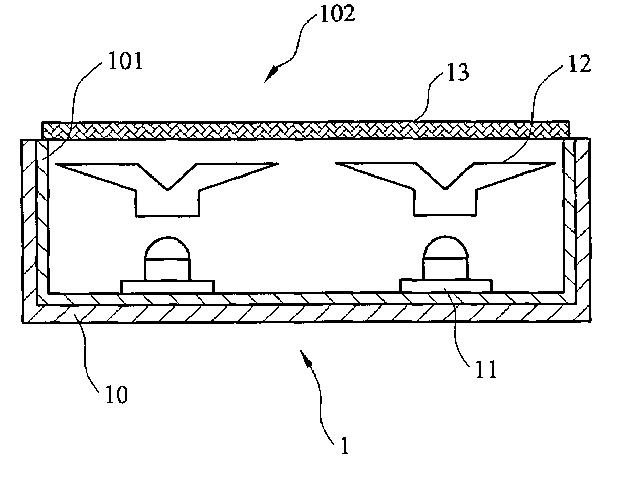
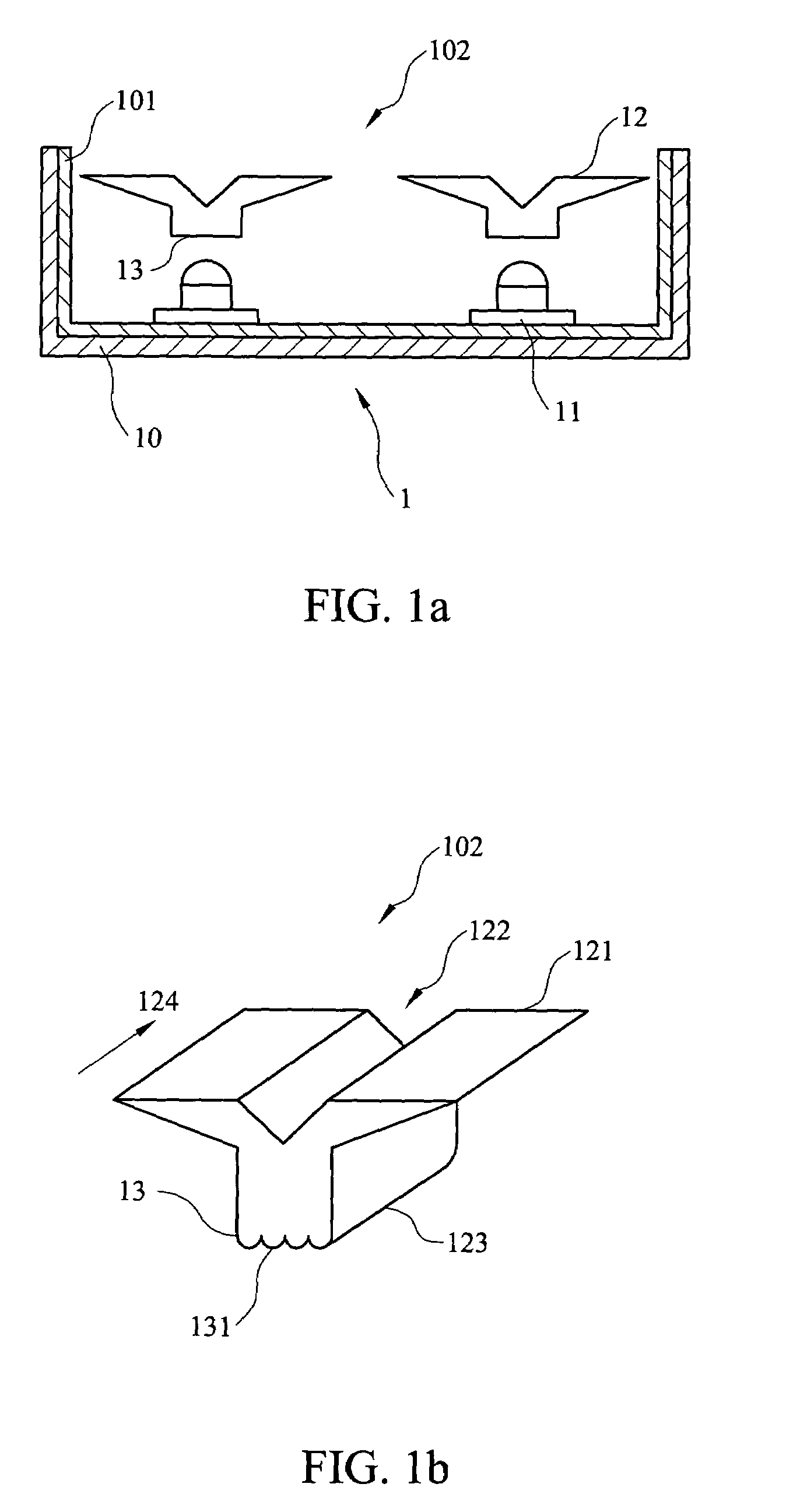
[0019]Referring to FIG. 1a and FIG. 1b, FIG. 1a is a schematic view illustrating an illumination apparatus in accordance with an embodiment of the present invention. The illumination apparatus 1 comprises a cavity 10, a light source 11, a light-spreading device 12 and a first optically-conditioning surface 13, wherein the cavity 10 comprises a diffusion surface 101 and a light-output area 102. The diffusion surface 101 is disposed on the interior side of the cavity 10, and the light source 11 emits light for the illumination apparatus 1. The light-spreading device 12 distributes the light emitted from the light source 11 so as to generate a uniform illumination.

[0020]When the light (not shown) emitted form the light source 11 strikes the diffusion surface 101, the light is scattered by the surface 101 and possibly uniformly distributed. Preferably, the diffusion surface 101 is substantially similar to a Lambertian surface. An observer viewing from any angle will detect the same inte...

second embodiment

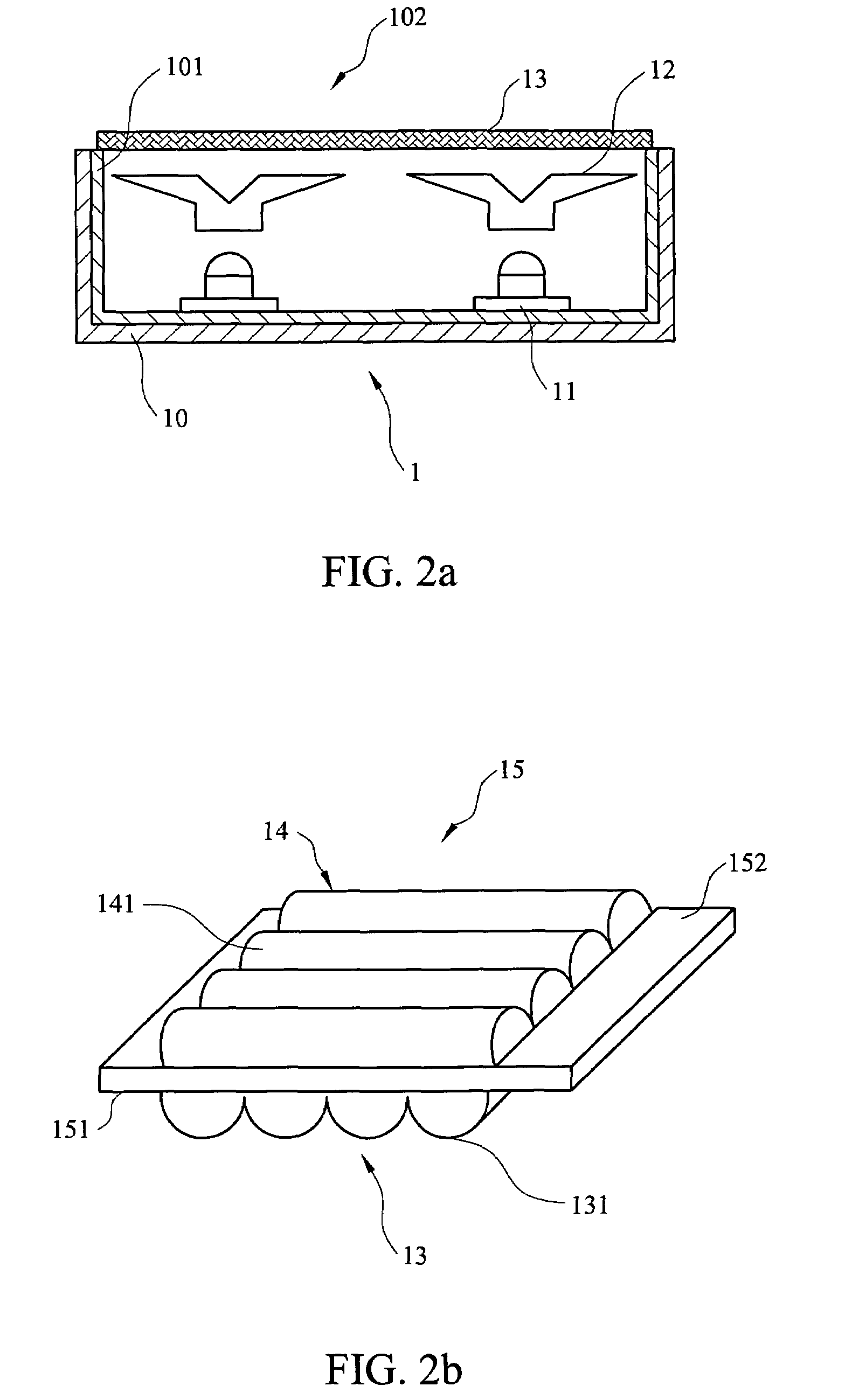
[0026]FIGS. 2a and 2b are schematic views illustrating an illumination apparatus in accordance with another embodiment of the present invention. It is noted that, in the second embodiment, the same references numbers are used for similar elements and are not described in detail again.

[0027]The illumination apparatus 1 optionally comprises an optical film 15 having a first surface 151 and a second surface 152 opposite to the first surface 151. The optically-conditioning surface 13 of the present embodiment is formed on the first surface 151 The optical film 15 can be disposed on the light-output area 102 of the illumination apparatus 1 or between the light-spreading device 12 and the light source 11. As described in the first embodiment, the optical film 15 is able to spread light. Optionally, a second optically-conditioning surface 14 can be formed on the second surface 152 of the optical film 15, and a second wavelike array 141 is also formed on the second optically-conditioning su...

third embodiment

[0029]FIGS. 3a and 3b are schematic view illustrating an illumination apparatus in accordance with another embodiment of the present invention. In the third embodiment, the same references numbers are used for similar elements in the first embodiment and are not described in detail again.

[0030]The light emitted from the light source 11 usually will not travel in one direction but radiate into the surroundings, therefore, it is likely that a portion of the light will directly enter the cavity 10 without passing through the light-spreading device 12. To collect the light not entering into the light-spreading device 12, the illumination apparatus 1 of the present invention includes a light-collecting element 16 for collecting the light emitted from the light source 11. The light-collecting element 16 is positioned between the light source 11 and the light-spreading device 12. Furthermore, the first optically-conditioning surface 13 can be formed on the light-collecting element 16. When...


PUM


Abstract

An illumination apparatus is disclosed in the invention. The illumination apparatus includes a cavity with a diffusion surface, a light source, a light-spreading device, and at least one optically-conditioning surface with a wavelike array formed thereon. The light-spreading device and the optically-conditioning surface spread the light generated by the light source. The light-spreading device includes a wing-shaped protrusion part, a light incident surface, a recess located away from the light incident surface, and an optically-conditioning surface including a wavelike array, wherein the wavelike array has a wavefront direction.

Description

RELATED APPLICATIONS[0001]The present application claims the right of priority based on Taiwan Application Serial Number 93129157, filed Sep. 24, 2004; and Taiwan Application Serial Number 94114630, filed May 6, 2005, the disclosures of which are incorporated herein by reference in their entireties.FIELD OF THE INVENTION[0002]The present invention relates to an illumination apparatus, and more particularly to a planar illumination apparatus having a light-spreading device.BACKGROUND OF THE INVENTION[0003]A liquid crystal display (LCD) is a non-self emitting display, i.e. it needs a self-emitting device to serve as a light source. Such a light source is generally called a backlight module. There are usually two types of backlight modules: a direct-light type and an edge-light type. A direct-light type backlight module conventionally includes components such as cold cathode tubes that serve as the light sources, a diffuser, a prism sheet, etc. In order to evenly distribute light emitt...

Claims


Application Information

Patent Timeline
Patent Type & Authority Patents(United States)
IPC IPC(8): G09F13/04F21S2/00F21V5/04
CPCF21V7/0091G02B6/0018G02B6/0021G02B6/0033G02B19/0071G02B19/0028G02B19/0061F21Y2101/02H01L2924/01322H01L2924/00F21Y2115/10Y10T428/31551G02F1/1335
Inventor HSIEH, MIN-HSUNYIN, CHOU-CHIHCHEN, CHUN-CHANGWANG, JEN-SHUITSAI, CHIA-FENCHEN, YI-MING
Owner EPISTAR CORP
Why Eureka
Try Eureka