Floor care appliance with tool caddy

Inactive Publication Date: 2008-04-01
HEALTHY GAIN INVESTMENTS
View PDF15 Cites 16 Cited by
  • Summary
  • Abstract
  • Description
  • Claims
  • Application Information

AI Technical Summary

Problems solved by technology

However, unknown in the art is a strictly bare floor cleaning appliance having an accessory hose and telescoping wand, and cleaning accessories for cleaning other bare surfaces, such as tile walls, shower walls, and hard-to-reach floor areas, such as behind toilets, as well as the grout between tiles.

Method used


Image

  • Floor care appliance with tool caddy
  • Floor care appliance with tool caddy
  • Floor care appliance with tool caddy

Examples


Embodiment Construction

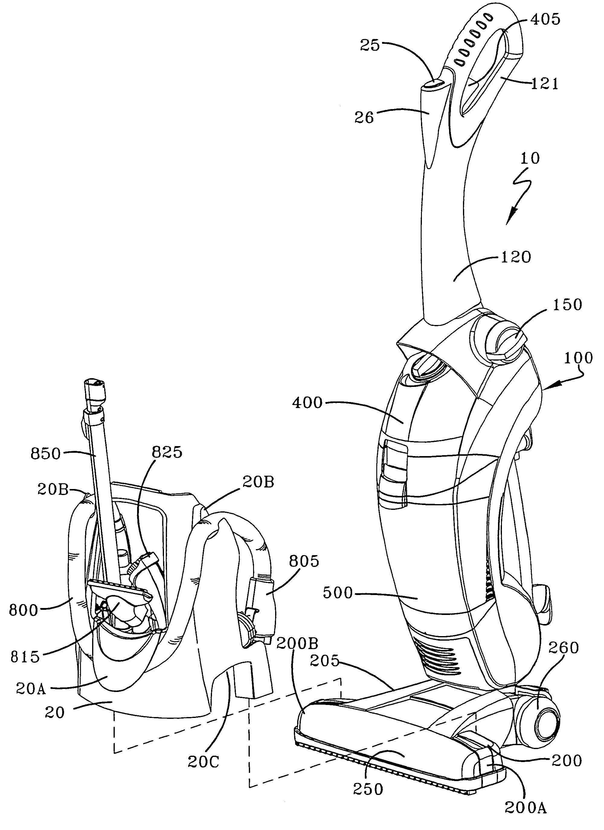
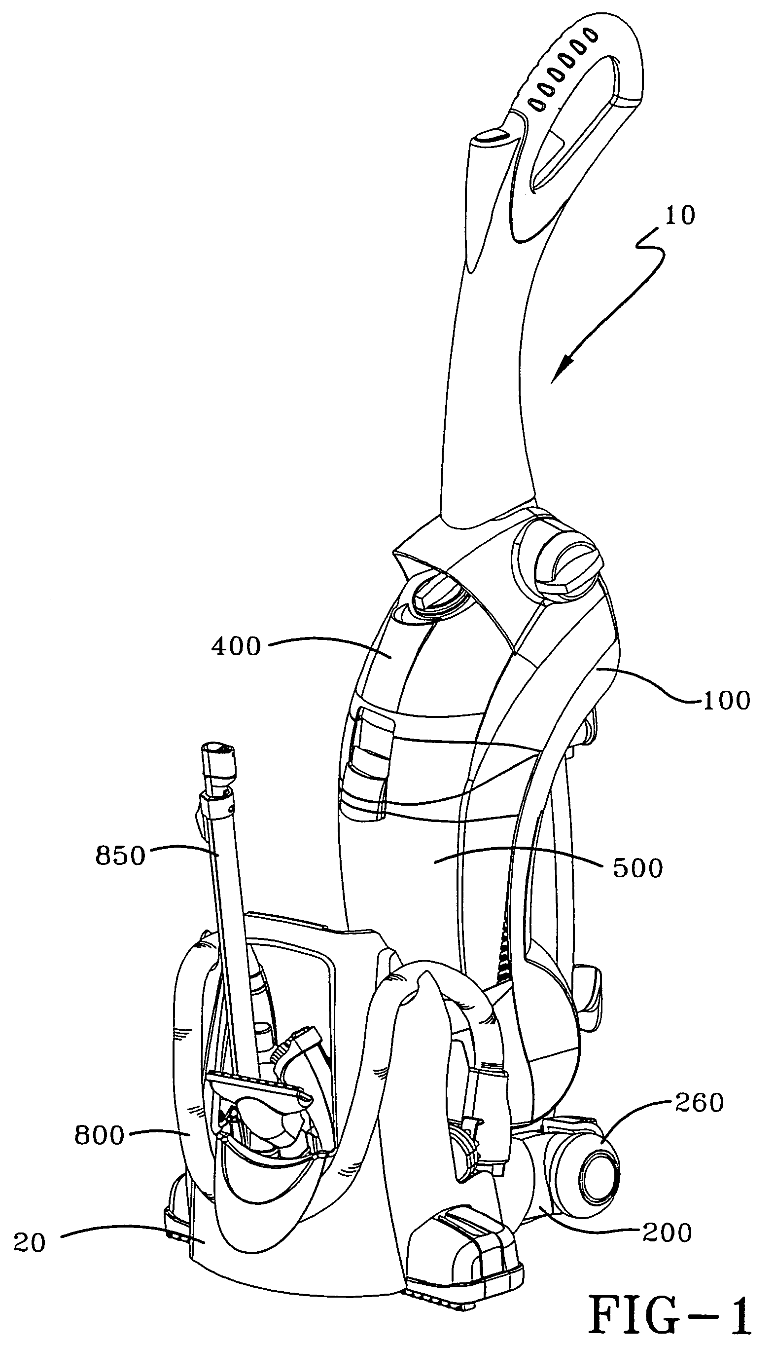
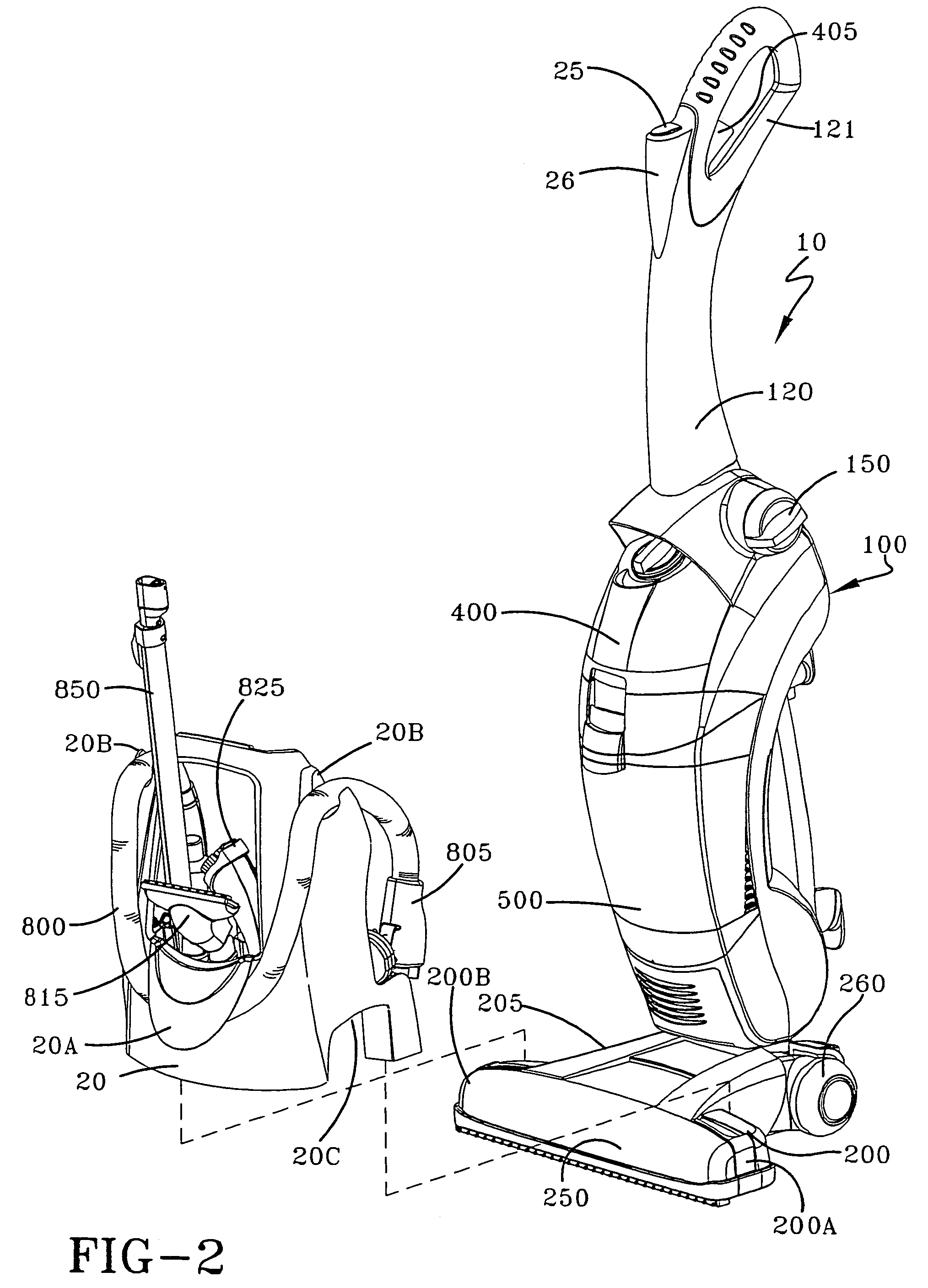
[0064]Referring to FIGS. 1 and 2, shown is a perspective view of an upright cleaning appliance 10 for cleaning bare surfaces such as floors and tile, according to one embodiment of the present invention. A similar upright cleaning appliance was disclosed in U.S. Pat. No. 6,640,386 owned by a common assignee and incorporated by reference fully herein. The upright floor care appliance 10 comprises an upright housing portion 100 pivotally connected to a base assembly 200 that is propelled over a bare floor surface for cleaning. A pair of trunnions (not shown) formed on the lower end of upright housing portion 100 are journaled into a complementary pair of bores (not shown) in a frame (not shown) partially forming base assembly 200 to form the pivotal connection. The trunnions are secured into the bores by a trunnion cover (not shown).

[0065]A combined air / liquid separator and recovery tank assembly 500 (hereinafter recovery tank assembly 500) and a cleaning solution storage tank assembl...


PUM


Abstract

A floor care appliance is provided for cleaning bare surfaces such as tile, marble, linoleum and wood. The floor care appliance includes an accessory caddy for storing an accessory hose, telescoping wand, cleaning implements and cleaning supplies. The accessory caddy is placed over the suction nozzle in front of the cleaner housing for storage. A pair of arcuate cutouts on the caddy are provided for placement over the suction nozzle. A handle is provided for transporting the accessory caddy.

Description

CROSS-REFERENCE TO RELATED APPLICATIONS[0001]This application is a divisional application of U.S. Ser. No. 10 / 990,837 filed on Nov. 17, 2004.BACKGROUND OF THE INVENTION[0002]1. Field of the Invention[0003]This invention relates to floor care appliances. More specifically, the present invention pertains to a bare floor cleaning appliance having an accessory caddy for storing the accessory hose, telescoping wand, and cleaning implements that are stored above the suction nozzle.[0004]2. Summary of the Prior Art[0005]Floor cleaning appliances having one or more cleaning modes are known in the art. Such appliances include both carpet and bare floor extractors. Typically, such floor cleaning appliances are comprised of a suction nozzle, a suction nozzle height adjustment mechanism, a motor-fan assembly, a liquid recovery system, one or more agitators, and controls for selecting the cleaning mode. One such bare floor cleaning appliance, as disclosed in U.S. Pat. No. 6,640,386 and incorpora...

Claims


Application Information

Patent Timeline
Patent Type & Authority Patents(United States)
IPC IPC(8): A47L9/00A47L5/30A47L5/32A47L5/34A47L9/28A47L11/34A47L11/40
CPCA47L5/225A47L5/30A47L5/32A47L5/34A47L9/0027A47L9/2842A47L9/2847A47L9/2857A47L11/34A47L11/4011A47L7/0004A47L9/0009A47L11/30A47L11/302A47L11/305A47L9/0494A47L9/0653
Inventor SCHEIFELE, KEVIN E.
Owner HEALTHY GAIN INVESTMENTS
Why Eureka
Try Eureka