Apparatus and method for treating process fluids

a technology for process fluids and apparatuses, applied in the direction of combustible gas purification/modification, machine/engine, separation process, etc., can solve the problems of high power requirements of many forms of such equipment, and high initial and maintenance costs of related equipment. , to achieve the effect of reliable, efficient and sustainabl

Inactive Publication Date: 2008-04-08
RUTSTEIN ALEX
View PDF12 Cites 26 Cited by
  • Summary
  • Abstract
  • Description
  • Claims
  • Application Information

AI Technical Summary

Benefits of technology

[0005]The main object of the present invention is to provide an efficient, reliable and inexpensive means and method for atomizing fluids.
[0006]Another object of the present invention is to provide an efficient, reliable and inexpensive means and method for producing high mass flow rate of aerosols.
[0007]Another object of the present invention is to provide an efficient, reliable, and inexpensive means and method for producing high mass flow rate of aerosol having micron and submicron mean droplet diameter sizes.

Problems solved by technology

While some of the known equipment is effective, many forms of such equipment have high power requirements.
Such nozzles production rate reduces drastically when small, sub micron to micron size droplets are required as well as posses other drawbacks.
Some related equipment, and especially gas compressors may have high initial and maintenance cost and the like.
Cost problems may be exacerbated if the required gas pressure is high.
If the rotating equipment is large and / or bulky, the cost factors can be even further worsened by large space requirements.
Vacuum pumps consume a lot of energy and are known to be heavy, bulky and expensive to operate.

Method used


Image

  • Apparatus and method for treating process fluids
  • Apparatus and method for treating process fluids
  • Apparatus and method for treating process fluids

Examples


Embodiment Construction

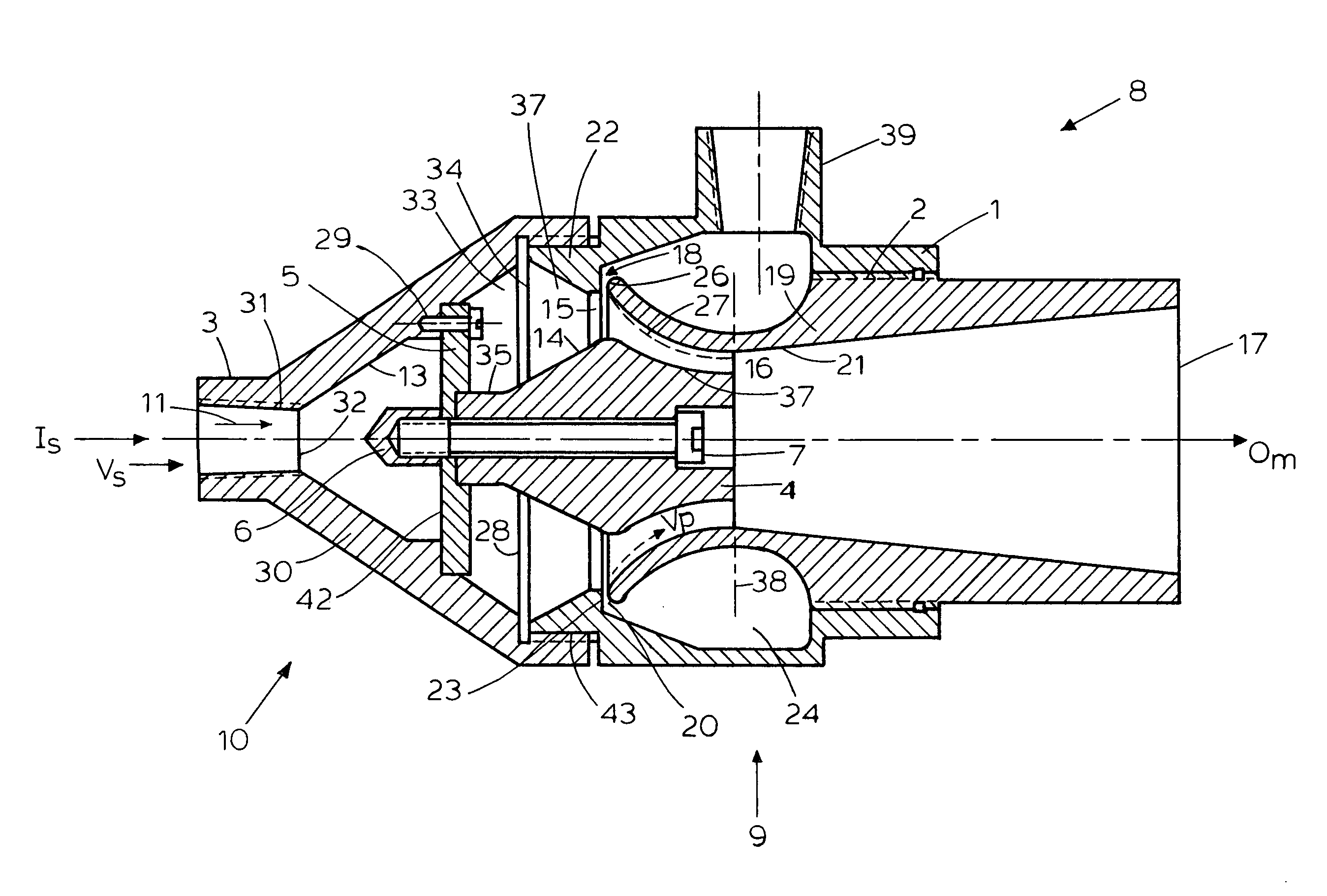
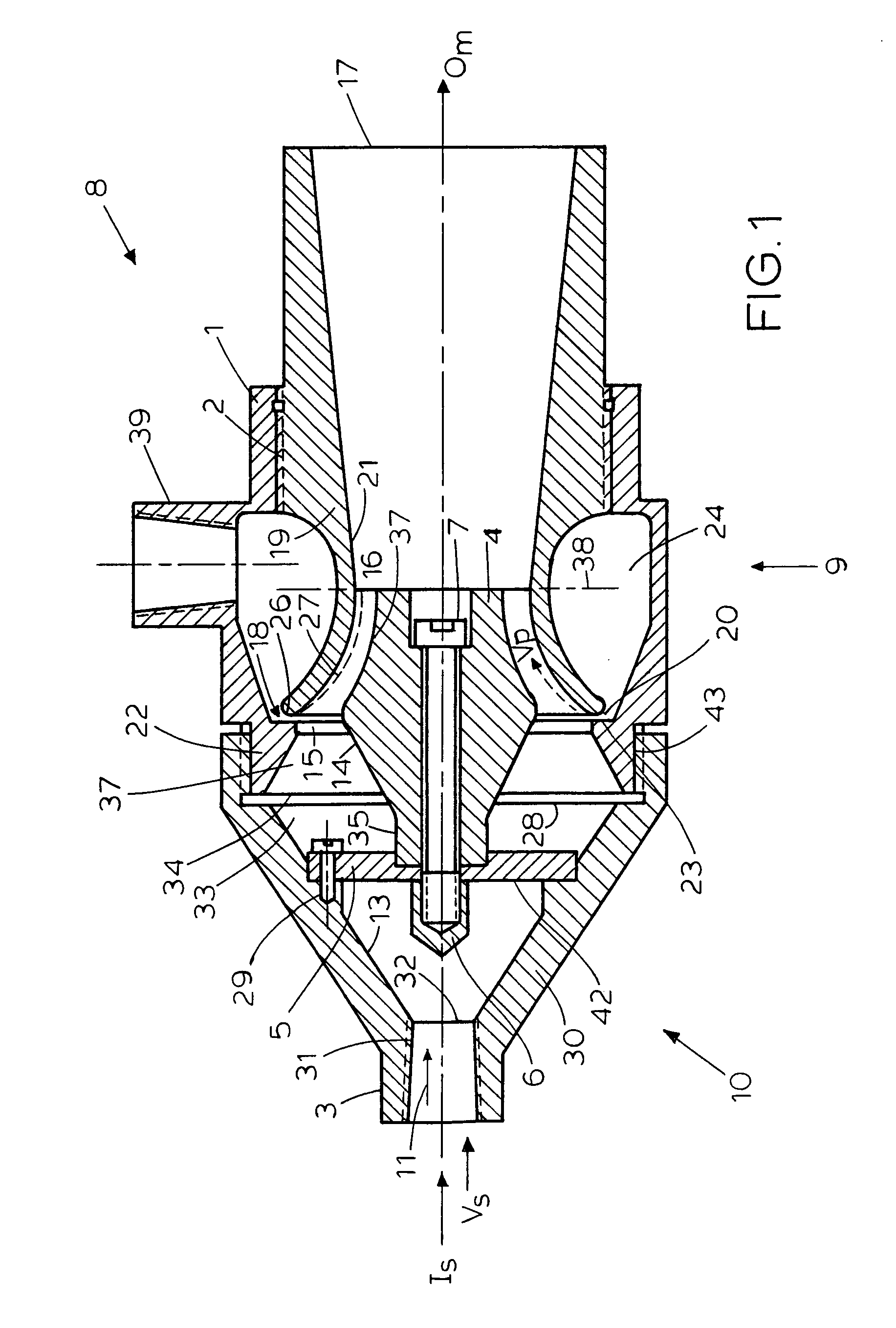
[0038]As shown in FIG. 1, a process fluid treating apparatus 8 embodying the present invention includes a Coanda ejector assembly 9 fluidically connected to a process fluid supply assembly 10, with a process fluid, a mixture of process fluids, and / or a mixture of process fluids and solids 11 flowing into the inlet port 12 of the process fluid supply assembly 10 in direction Is, passing through windows provided in the support plate 5 of an insert 4, and being turned by the inner walls 13 of the process fluid supply assembly 10 and the ascending outer walls 14 of the specially profiled insert 4 toward the annular entrance 15 into the process treating channel 16, with a mixture flowing out of an exit 17 of the Coanda ejector assembly in direction 0m. As used hereinabove, the term “mixture” means the primary fluid 18 and process fluid 11. The fluid exiting the ejector assembly has typically near-ambient pressure. It is noted that the passageway 16 enables ejector assembly 9 to provide s...


PUM

PropertyMeasurementUnit
apex angleaaaaaaaaaa
pressureaaaaaaaaaa

Abstract

A process fluid treating apparatus includes an ejector assembly fluidically connected to a process fluid supply assembly. A Coanda airfoil is located in the ejector assembly. Primary fluid is injected into the ejector duct to form a Coanda layer. A process fluid, or part of it, flows toward the ejector assembly through the process fluid assembly, which gradually turns that process fluid towards fluid treating channel formed adjacent to the Coanda layer. Shear and other forces and pressure gradients associated with the Coanda layer serve to pump or assist in pumping the process fluid from the source and to operate on the process fluid to atomize it, to pulverize, or de-agglomerize solid particles entrained in the process fluid, to produce high mass flow rate of the process fluid and to provide aerosol down to micron and sub micron mean droplet diameter size.

Description

CROSS REFERENCE TO RELATED APPLICATIONS[0001]The present application claims priority of Provisional Application Ser. No. 60 / 575,164 filed by the present inventor on May 28, 2004. The disclosure of the just-mentioned Provisional Application is fully incorporated herein by reference.TECHNICAL FIELD OF THE INVENTION[0002]The present invention relates to the general art of fluid handling and fluid treating, and to the particular field of means and methods for pumping, atomizing fluids, pulverizing, or de-agglomerizing solids in mixtures of fluids and / or mixtures of fluids and solids.BACKGROUND OF THE INVENTION[0003]Many industrial processes require aerosolizing of fluids, or treating of a mixture of fluids and / or fluids and solids. Treatment of a fluid, a mixture of fluids, or a mixture of fluids and solids can be in the form of atomizing the liquid and pulverizing or de-agglomerizing the solids carried by the fluid. Current means and methods for effecting such treatment include, among ...

Claims


Application Information

Patent Timeline
Patent Type & Authority Patents(United States)
IPC IPC(8): B01F3/04
CPCB01F3/12B01F5/0293B01F5/0413B01F5/0428F04F5/46F04F5/463Y10S239/07B01F23/50B01F25/282B01F25/31242B01F25/312
Inventor RUTSTEIN, ALEX
Owner RUTSTEIN ALEX
Why Eureka
Try Eureka