Low profile flip up site

a low-profile, flip-up site technology, applied in the field of modular weapons sighting devices, can solve the problems of affecting the affecting the accuracy of field use of firearms, so as to achieve accurate and consistent aiming, streamlining the profile of weapons, and simple movement of fingers or thumbs

Active Publication Date: 2008-04-15
SWAN RICHARD E
View PDF44 Cites 89 Cited by
  • Summary
  • Abstract
  • Description
  • Claims
  • Application Information

AI Technical Summary

Benefits of technology

[0007]In this regard, the present invention provides for a low-profile self-aligning flip-up sight. The present invention sighting device folds downwardly against a mounting rail either directly on the fire arm, onto a receiver sleeve mounting area or other desirable location, thereby keeping the sighting device within the firearm's contour during non-use and streamlining the profile of a weapon. The sighting device is spring-loaded and flips into an operational position with a simple movement of a finger or thumb. The device includes a pair of iron sights that are also pivotally mounted relative to one another allowing them to fold against one another in the retracted position while moving into a position wherein the two sighting elements are oriented at a substantially 90° angle in the deployed position. Further, the present invention sighting device self-aligns itself as it moves into an operational position, thereby providing accurate and consistent aiming while eliminating the need for re-alignment each time the sight is deployed.
[0010]Accordingly, it is an object of the present invention to provide a sighting mechanism for a firearm that includes at least two aiming elements and has a compact profile when placed into a storage position. It is a further object of the present invention to provide a sighting mechanism for a firearm that can be retracted to a low profile storage position against the contour of the firearm while being quickly and easily deployable to a fully aligned active position. It is yet a further object of the present invention to provide a retractable sighting assembly for a firearm that includes at least two user selectable aiming elements that can be fully retracted into a low profile storage position against the contour of the firearm.

Problems solved by technology

Generally, sighting mechanisms for firearms are bulky and protrude outside the firearm's general contour.
This construction creates a greater opportunity for the sighting mechanism to be caught on clothing or brush while the fire arm is being carried thereby knocking the sighting mechanism out of alignment.
Although this re-alignment step may be acceptable when the firearm is used in a controlled environment such as a firing range, it is not acceptable for a firearm employed for field use, such as hunting or combat environments where immediate, fully aligned use of the sight is required.
However, this device has a relatively large vertical profile, even when it is in the retracted position.
If the iron sight assembly is not in this position, the mechanism cannot be moved into the storage position.

Method used


Image

  • Low profile flip up site
  • Low profile flip up site
  • Low profile flip up site

Examples


Embodiment Construction

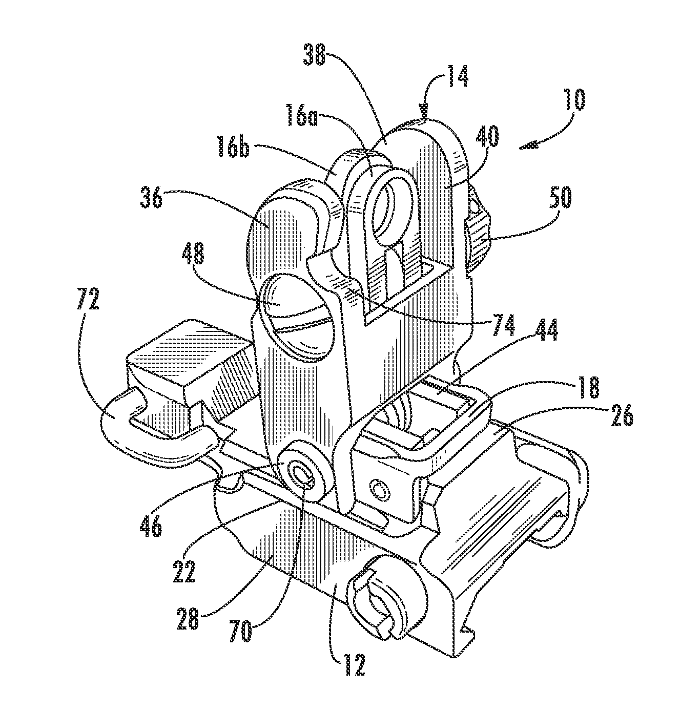
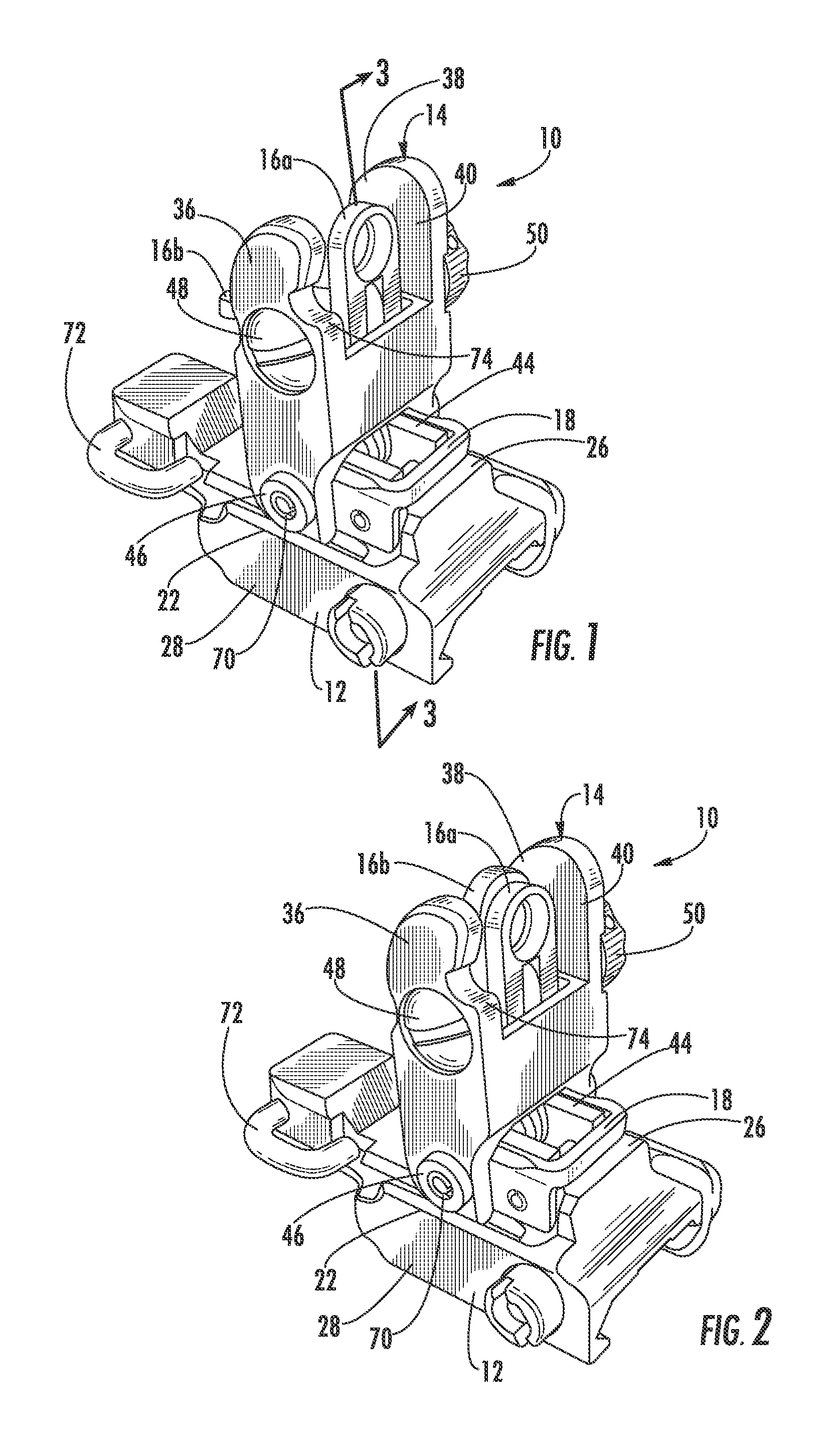
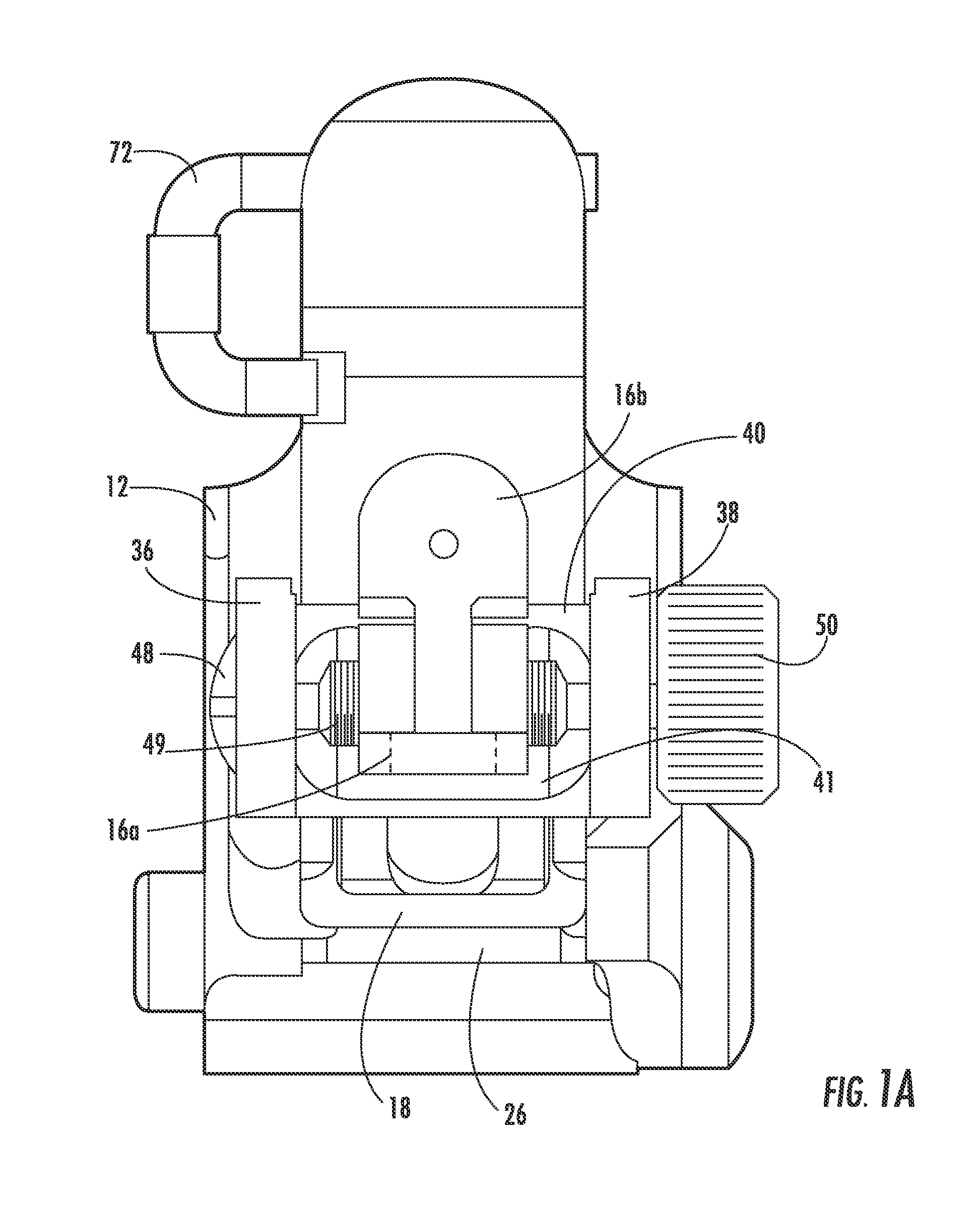
[0023]Now referring to the drawings, the retractable flip-up sighting device of the present invention is shown and generally illustrated in the figures as 10. In particular, the present invention is a retractable flip-up sight 10 for a fire arm wherein the flip-up sight 10 has a reduced profile when in the retracted position. This feature allows improved shielding and protection of the aiming elements within the sighting device 10 when in the retracted storage position. Further, the sighting device 10 includes a self-aligning feature that ensures that the sighting elements remain in proper alignment with the firearm each time the sighting elements are deployed into the active position from the storage position. The flip-up sight assembly includes three major components: a base 12, a sight housing 14, and an aiming device 16. Further, to facilitate the self-aligning feature, the sighting device 10 includes an alignment member 18. The sight housing 14 serves to contain and support the...


PUM


Abstract

A low profile, self-aligning, flip-up mechanism for aiming devices used with firearms. The mechanism folds the aiming device into the contour of the firearm during non-use. The mechanism is spring-loaded and flips into a vertical operational position with a simple movement of a finger or thumb. The mechanism includes at least two separate aiming elements that are mounted in a fashion that allows them to rotate relative to one another thereby facilitating a smaller storage profile. The mechanism also causes the aiming device to self-align itself as it moves into an operational position assuring vertical position repeatability.

Description

CROSS-REFERENCE TO RELATED APPLICATIONS[0001]This application is related to and claims priority from earlier filed U.S. Provisional Patent Application No. 60 / 511,878, filed Oct. 16, 2003, the contents of which are fully incorporated herein by reference.BACKGROUND OF THE INVENTION[0002]The present invention relates generally to modular sighting devices for weapons. More specifically, the present invention relates to a low profile configuration for a for providing a flip-up type sighting mechanism that folds down onto the firearm in a compact manner to prevent damage or snagging when not in use.[0003]Generally, sighting mechanisms for firearms are bulky and protrude outside the firearm's general contour. This construction creates a greater opportunity for the sighting mechanism to be caught on clothing or brush while the fire arm is being carried thereby knocking the sighting mechanism out of alignment. Prior art devices that have attempted to address this problem by allowing removal ...

Claims


Application Information

Patent Timeline
Patent Type & Authority Patents(United States)
IPC IPC(8): F41A15/00F41G1/06F41G1/08F41G1/17
CPCF41G1/065F41G1/08F41G1/17
Inventor SWAN, RICHARD E.
Owner SWAN RICHARD E
Why Eureka
Try Eureka