Camera device and vehicle periphery monitoring apparatus

a technology for monitoring equipment and cameras, which is applied in the direction of picture signal generators, television systems, transportation and packaging, etc., can solve problems such as inability to pick up

Inactive Publication Date: 2008-04-15
AUTONETWORKS TECH LTD +2
View PDF17 Cites 10 Cited by
  • Summary
  • Abstract
  • Description
  • Claims
  • Application Information

AI Technical Summary

Benefits of technology

[0015]It is therefore an object of the invention to provide a camera device and a vehicle periphery monitoring apparatus in which the intervention of a member for supporting an optical device in the image can be minimized.

Problems solved by technology

However, in the camera device 100 shown in FIG. 8, there is a problem in that the ineffective region VR, where an image cannot be picked up, is generated between the upper region Vu and the lower region Vd, and a relatively large ineffective region 146 is generated between the images of the visual fields 142L and 142R on the left and the right front sides and the visual field on the lower front side 144.

Method used


Image

  • Camera device and vehicle periphery monitoring apparatus
  • Camera device and vehicle periphery monitoring apparatus
  • Camera device and vehicle periphery monitoring apparatus

Examples


Embodiment Construction

[0028]Referring now to the accompanying drawings, a description will be given in detail of a preferred embodiment of the invention.

[0029]A vehicle periphery monitoring apparatus according to an embodiment of the present invention will be described hereinbelow.

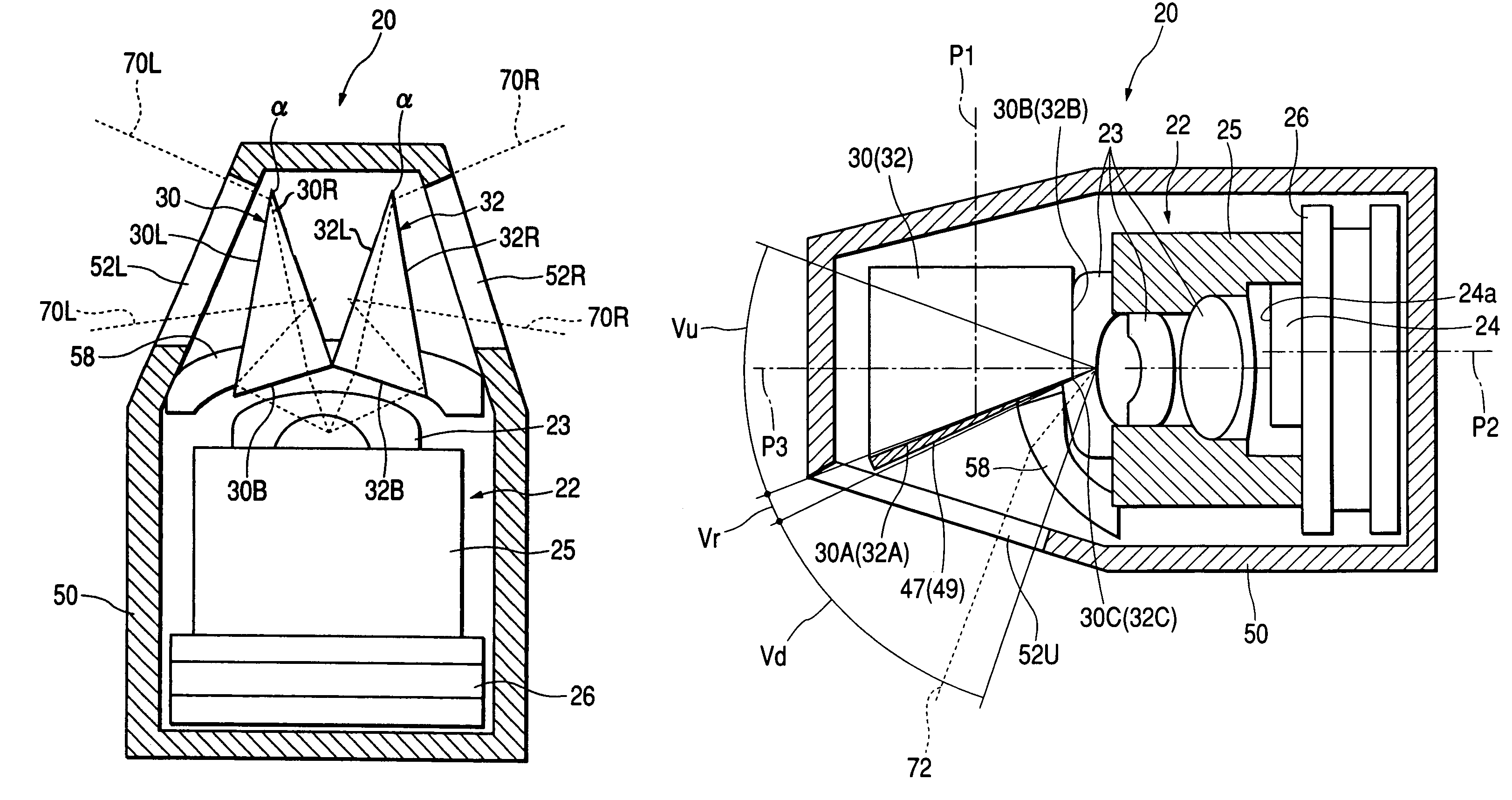
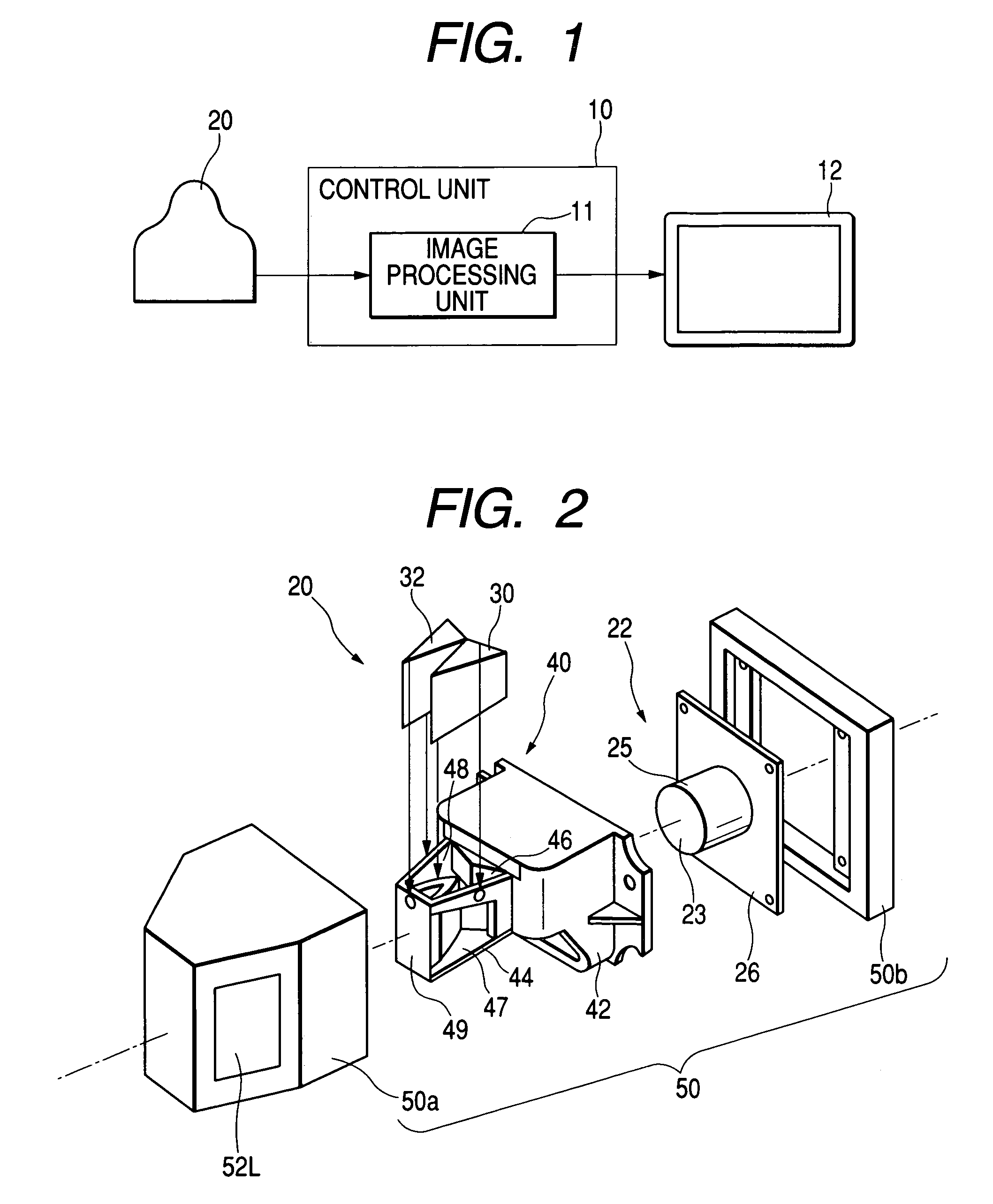
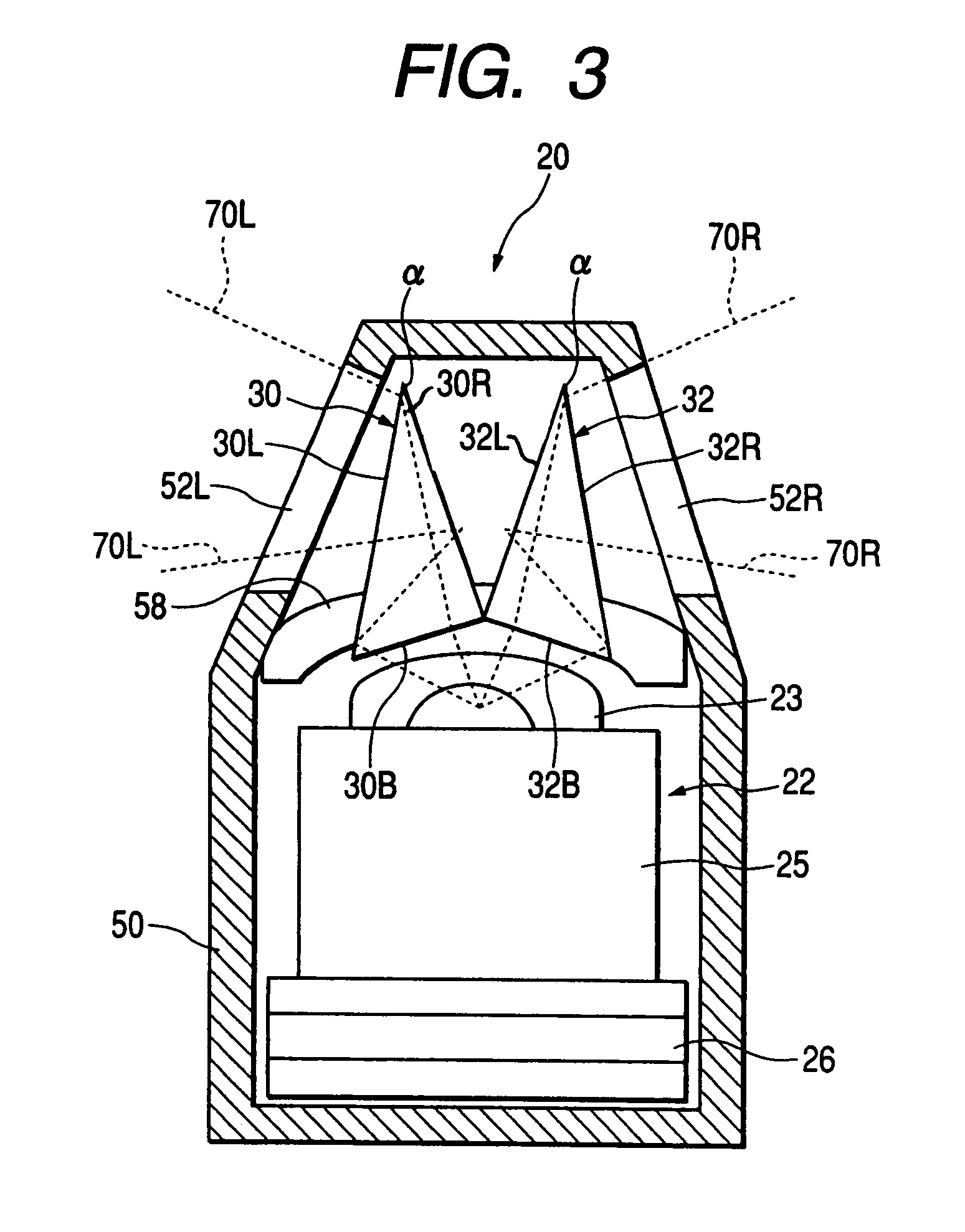
[0030]FIG. 1 is a schematic drawing of a vehicle periphery monitoring apparatus; FIG. 2 is an exploded perspective view of a camera device included in the vehicle periphery monitoring apparatus; FIG. 3 is a plan schematic drawing of the camera device; FIG. 4 is a side schematic drawing of the camera device; and FIG. 5 is a drawing showing an example of a display image of the vehicle periphery monitoring apparatus.

[0031]As shown in FIG. 1, the vehicle periphery monitoring apparatus includes a single camera device 20, a control unit 10 having an image processing unit 11 for performing a predetermined image processing, and a display device 12, such as a liquid crystal image device installed in a vehicle cabin.

[0032]The camera devi...


PUM


Abstract

A pair of left and right prisms are disposed on part of the region in front of the image pickup unit. A wide-angle lens is disposed on another part of region in front of the image pickup unit. Tapered supporting members of a prism holder for supporting the prisms located between the prisms and the wide-angle lens are formed so as to be reduced in thickness gradually toward the image pickup unit.

Description

BACKGROUND OF THE INVENTION[0001]1. Field of the Invention[0002]The present invention relates to a camera device for imaging a plurality of directions in the visual field simultaneously and a vehicle periphery monitoring apparatus using the camera device.[0003]2. Description of the Related Art[0004]There is proposed a camera device capable of imaging a plurality of directions in the visual field simultaneously as shown in FIG. 8.[0005]A camera device 100 includes an image pickup unit 101 having a single image pickup device 110 and an image pickup lens 112 disposed in front of the image pickup device 110.[0006]A prism 120 is disposed in front of the image pickup unit 101 on the upper side. Incident beams entering from both of the left and the right sides are guided by the prism 120 toward the image pickup unit 101 so that an image is formed on the image pickup device 110 via the image pickup lens 112.[0007]A wide-angle lens 122 is disposed in front of the image pickup unit 101 on the...

Claims


Application Information

Patent Timeline
Patent Type & Authority Patents(United States)
IPC IPC(8): H04N7/00H04N5/225H04N7/18H04N9/07H04N9/47B60R1/00B60R1/10
CPCB60R1/00B60R1/10H04N7/18B60R2300/30B60R2300/802
Inventor IMOTO, MASAYOSHI
Owner AUTONETWORKS TECH LTD
Why Eureka
Try Eureka