Integrated control card for conveying systems

a control card and conveying system technology, applied in the field of conveying systems, can solve the problems of high labor intensity, high labor intensity, and high labor intensity of installation and commissioning of prior conveying systems, and achieve the effect of consuming a significant amount of labor and time for installation of conveying systems

Active Publication Date: 2008-04-22
KÖRBER SUPPLY CHAIN LLC
View PDF17 Cites 47 Cited by
  • Summary
  • Abstract
  • Description
  • Claims
  • Application Information

AI Technical Summary

Problems solved by technology

The installation and commissioning of prior conveying systems has typically been a labor-intensive process.
In addition to significant amounts of labor, such custom engineering and design requires extra time for the custom-designed parts and system components to be manufactured.
The installation of conveying systems has therefore consumed a significant amount of both labor and time, all of which translate into increased costs for the customer of the conveying system.
As noted above, one of the labor-intensive processes has been installation of controls for the conveying system.

Method used


Image

  • Integrated control card for conveying systems
  • Integrated control card for conveying systems
  • Integrated control card for conveying systems

Examples


Embodiment Construction

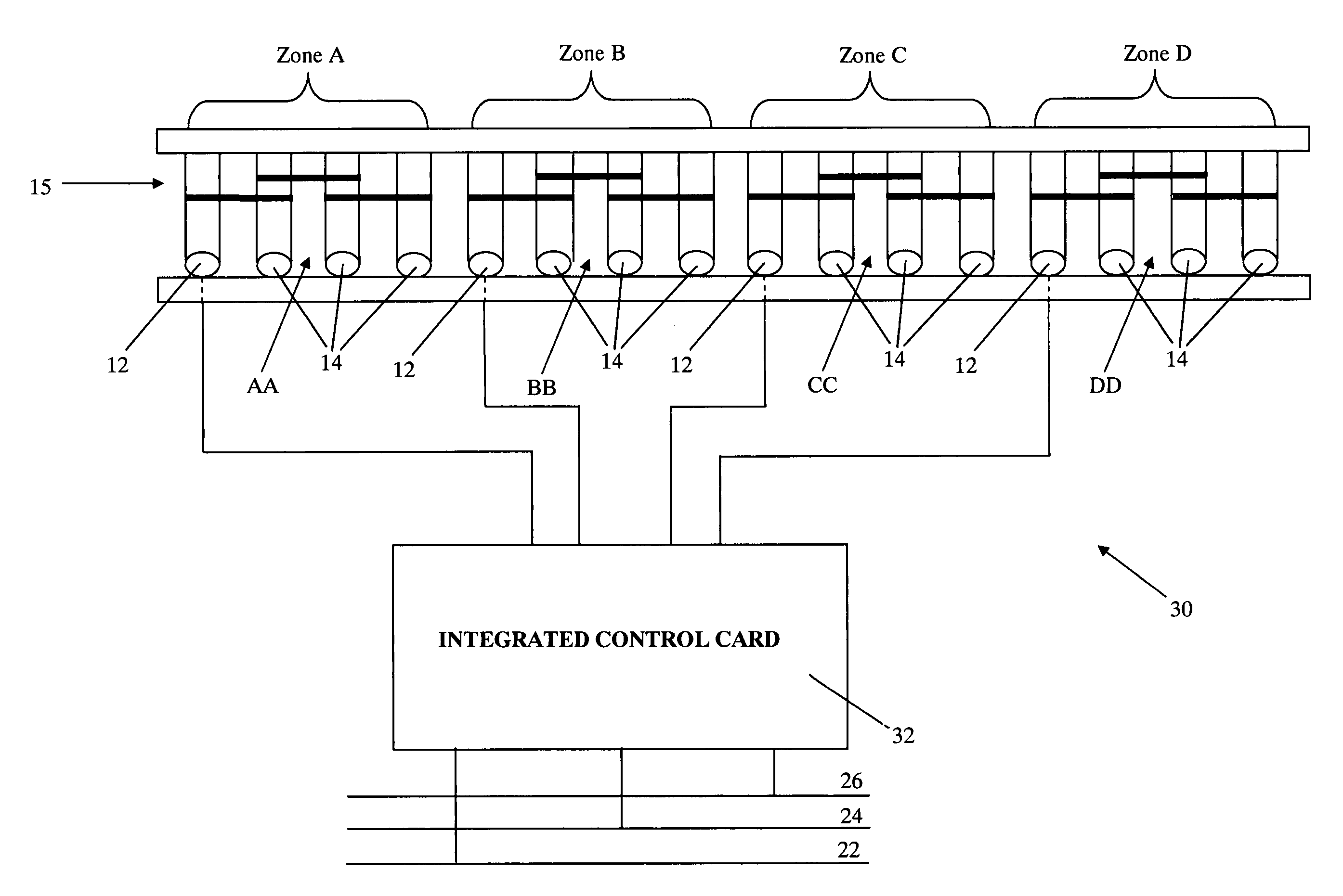
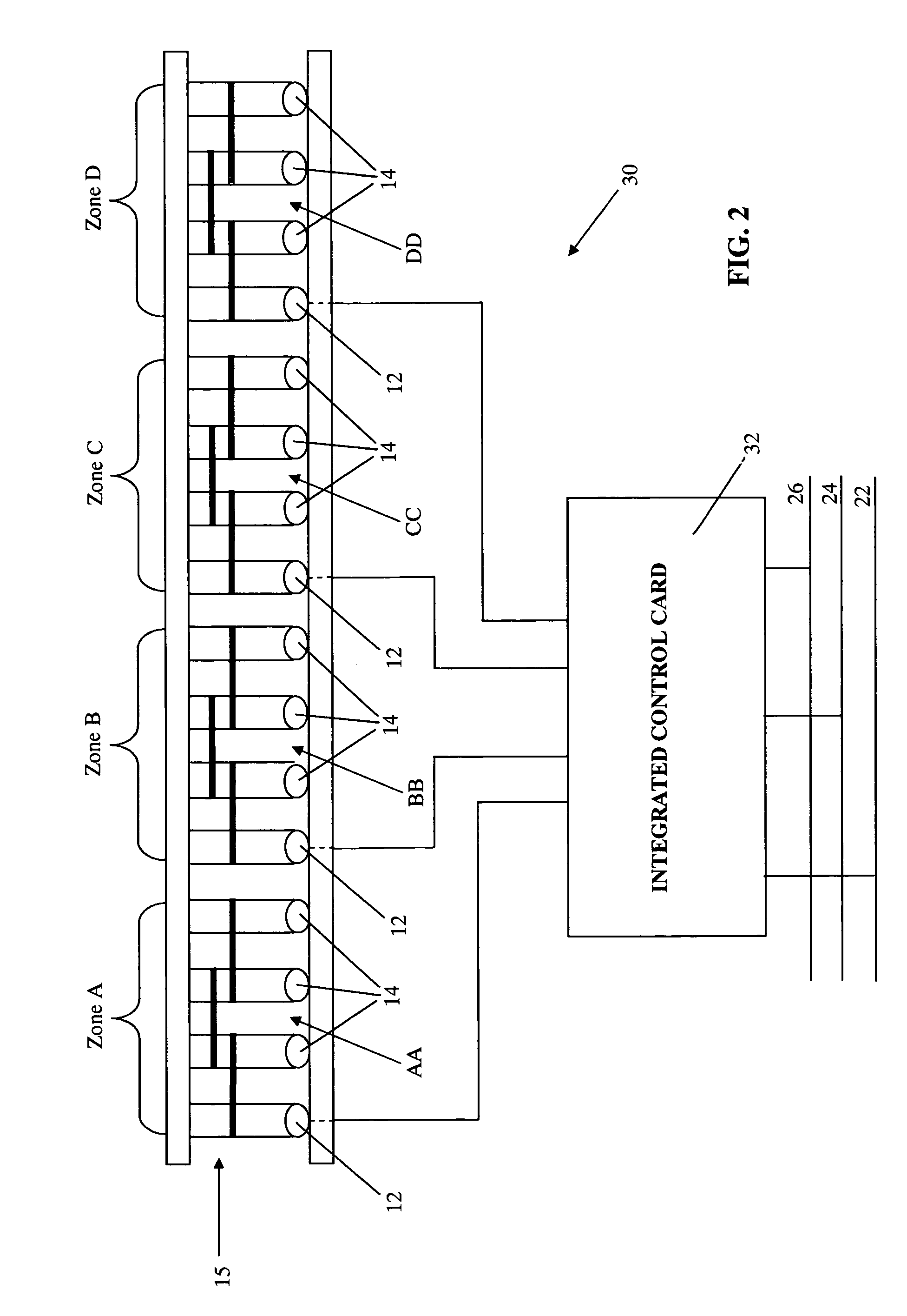
[0026]Referring now to the drawings and the illustrative embodiments depicted therein, conveying control system 30 of the illustrated embodiment utilizes an integrated control card 32 (FIG. 2). In the illustrative embodiment of FIG. 2, conveying control system 30 is illustrated to include a straight conveyor assembly 15 with four zones A-D, beds or sections, hereinafter “zones”, for conveying trays, boxes, or products, hereinafter generally referred to as “trays”. It must be appreciated, that the present invention applies to a plurality of conveyor configurations including, but not limited to, curved conveyors, merge conveyors, divert conveyors, or transfer conveyors, which will be discussed in further detail below. Additionally, the present invention may also apply to tray management material handling systems. Such a tray management system is disclosed in commonly assigned U.S. Pat. No. 6,561,339 issued to Olson et al. and entitled AUTOMATIC TRAY HANDLING SYSTEM FOR SORTER, the dis...


PUM


Abstract

A material handling system, and method of controlling the material handling system, includes a conveying surface with a plurality of individually controlled zones and a plurality of motors. At least one of the motors propelling the conveying surface at each zone. A plurality of motor controller circuits adapted to control the plurality of motors. An upper-level control circuit in communication with the plurality of motor controller circuits and adapted to send communications to the motor controller circuits for controlling at least one motor. An integrated control card defining the upper-level control circuit and the plurality of motor controller circuits, wherein the upper-level control circuit and the plurality of motor controller circuits are integrated onto the integrated control card.

Description

CROSS REFERENCE TO RELATED APPLICATION[0001]The present application claims priority of U.S. provisional application Ser. No. 60 / 522,029 filed Aug. 4, 2004, by Ko et al. for INTEGRATED BED CONTROLLER, which is hereby incorporated herein by reference in its entirety. The present application also claims priority to U.S. provisional application Ser. No. 60 / 663,038 filed Mar. 18, 2005, by Ko et al. for INTEGRATED BED CONTROLLER, which is hereby incorporated herein by reference in its entirety.BACKGROUND OF THE INVENTION[0002]The present invention relates generally to conveyors, and more particularly controls for electrically operated conveyor beds.[0003]Conveyor systems are used in a wide variety of material handling applications. These includes such things as conveying luggage throughout airports, conveying parcels through transportation terminals, conveying manufactured parts or components throughout factories, conveying inventory, sorting and conveying items to be transported, and var...

Claims


Application Information

Patent Timeline
Patent Type & Authority Patents(United States)
IPC IPC(8): B65G43/10B65G13/06G06F17/00
CPCG05B19/414H01R27/00
Inventor KO, CLYDE MIIN-ARNGCARLSON, RANDALL JSINEN, ROGER LTRIESENBERG, THOMAS HLEMKE, DONALD E
Owner KÖRBER SUPPLY CHAIN LLC
Why Eureka
Try Eureka