
Handheld tactical devices

a tactical device and hand-held technology, applied in the direction of manufacturing tools, repellant gas/chemical self-defence devices, lighting and heating devices, etc., can solve the problems of inability to adapt to hand-to-hand combat against an opponent in the past, and achieve the effect of reducing the risk of injury and avoiding injury

Active Publication Date: 2008-04-22
SUREFIRE LLC
View PDF29 Cites 17 Cited by
  • Summary
  • Abstract
  • Description
  • Claims
  • Application Information

AI Technical Summary

Benefits of technology

The present invention provides a handheld tactical device combining a weapon with a temporarily disabling emission generator. The emission generator can be actuated by the user to temporarily disable the opponent while in hand-to-hand combat. The device includes a handle with a securement device for attaching the emission generator, a tubular handle for accommodating the emission generator, and a retainer for securing the emission generator to the handle. The device also includes a flashlight or chemical spray device for added tactical advantage. The technical effect of the invention is to provide a handheld tactical device with a temporarily disabling emission generator that can be used in hand-to-hand combat to gain a tactical advantage over the opponent.

Problems solved by technology

Such combination apparatus in the past, however, have not been adaptable as tactical devices for hand-to-hand combat against an opponent.

Method used


Image

  • Handheld tactical devices
  • Handheld tactical devices
  • Handheld tactical devices

Examples


embodiment 20

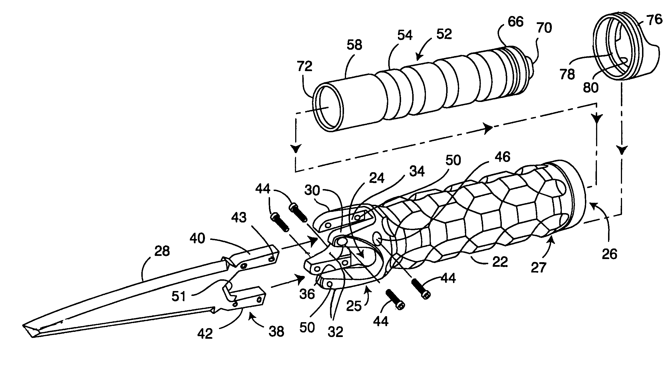
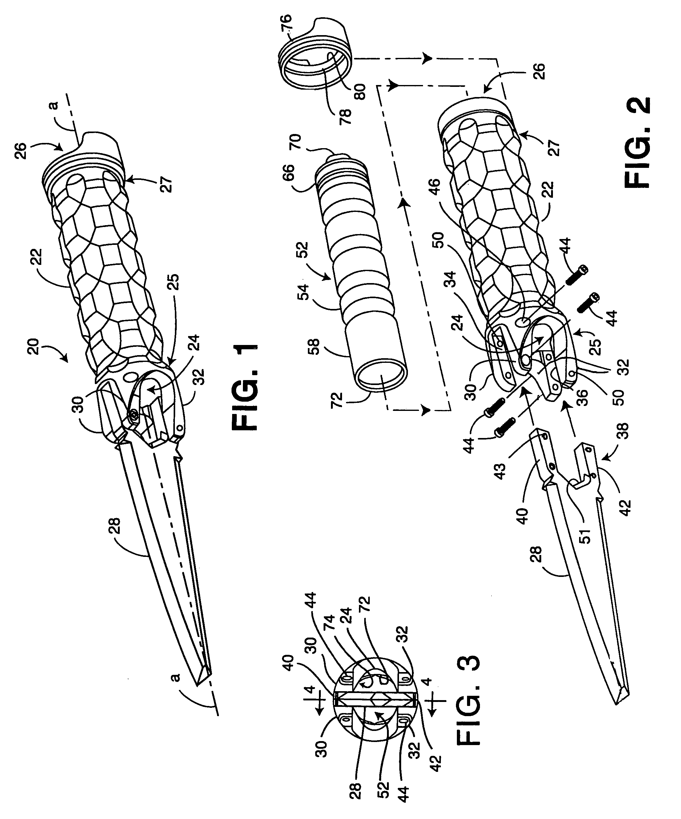
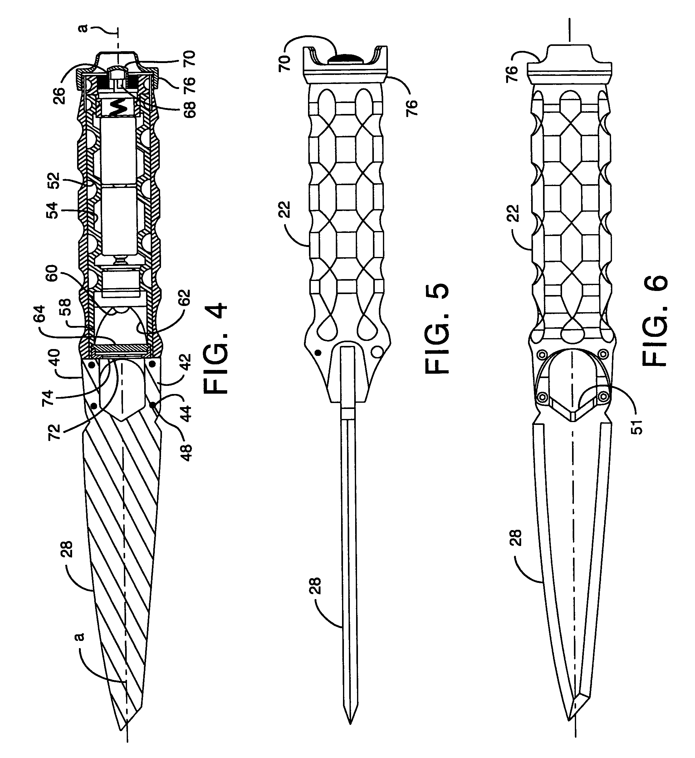
[0038]For example, turning to FIGS. 1-6, a preferred knife embodiment 20 includes a generally tubular handle 22 extending along a longitudinal axis a and including a first or front opening or window 24 at the handle's first or front end portion 25 and a second or rear opening 26 at the handle's second or rear end portion 27.

[0039]As used herein, except where otherwise evident from the context, the word “longitudinal” means a direction along or parallel to the longitudinal axis a of the handle 22 or a direction along or parallel to the longitudinal axis a of the spray device 84; “front” or “forward” describes a longitudinal direction toward the distal end of a weapon component attached to the handle 22 (e.g., to the left as shown in FIGS. 1, 2, 4-8 and 11-14); “rear” or “rearward” describes the direction opposite the front (e.g., to the right as shown in the drawing of FIGS. 1, 2, 4-8 and 11-14); “above” or “upper” means vertically above when the handle 22 is held horizontally; and “...

embodiment 120

[0058]Another preferred embodiment of the present invention, specifically a baton or truncheon combined with an emission generator such as a flashlight, is shown in FIGS. 15 and 16. A preferred baton embodiment 120 includes a generally tubular handle—preferably the previously described handle 22—extending along the longitudinal axis a and including the front opening or window 24 at the handle's front end portion 25 and a rear opening 26 at the handle's rear end portion 27.

[0059]The handle's front end portion 25 is configured for securely holding a baton body 122 in such manner that the front opening 24 is not significantly obstructed. In similar manner as previously described with respect to the knife blade 28 being held by the handle 22, the preferred handle front end portion 25 includes, outwardly of the front opening 24, two first or upper longitudinal forwardly-directed projections 30 transversely separated by a first or upper longitudinal slot 34, and two second or lower longit...


PUM


Abstract

Handheld tactical devices combining a weapon with an emission generator, and specifically combinations of a tubular handle with a detachably securable knife blade or baton body, together with a flashlight or chemical spray device removably insertable in the tubular handle. The preferred spray device embodiment emits dual sprays and includes a thumb-operable cover for permitting a user to both expose and depress the spray device's pushbutton actuator for instantly actuating the spray device.

Description

CROSS REFERENCE TO RELATED APPLICATION[0001]This application claims the benefit of U.S. Provisional Application No. 60 / 647,048, filed Jan. 25, 2005, which application is incorporated herein by reference.BACKGROUND OF THE INVENTION[0002]This invention relates to handheld tactical devices, and more particularly to systems for attaching two tactical devices to one another for being held by a person.[0003]Apparatus combining a handle with various objects, such as tools, culinary utensils and knives, are generally well know. Examples of patents disclosing such combinations are described in the following U. S. Pat. Nos. 1,144.210; 1,361,021; 1,439,404; 1,868,778; 2,242,536; 2,674,685; 3,510,643; 4,669,186; 5,857,268; 6,135,608; 6,336,731; 6,511,199; Des. 412,096 and Des. 412,355.[0004]Such combination apparatus in the past, however, have not been adaptable as tactical devices for hand-to-hand combat against an opponent.SUMMARY OF THE INVENTION[0005]The present invention provides handheld ...

Claims


Application Information

Patent Timeline
Patent Type & Authority Patents(United States)
IPC IPC(8): F21V33/00
CPCF21V33/0064F41B13/08F41G1/35F41H9/10
Inventor KIM, PAUL Y.
Owner SUREFIRE LLC
Learn More