Apparatus for forming an air spring flexible member

a flexible member and air spring technology, applied in the field of apparatus for forming air spring flexible members, can solve the problems of inability to use clamp ends for further use, inability to reduce the amount of blank at both ends, and inability to reduce the amount of blanks, so as to reduce vulcanization errors, reduce cost and quality, and double productivity

Inactive Publication Date: 2008-04-22
CONTITECH LUFTFEDERSYST
View PDF3 Cites 0 Cited by
  • Summary
  • Abstract
  • Description
  • Claims
  • Application Information

AI Technical Summary

Benefits of technology

[0008]The basic advantage of the invention is that there is a reduction of the vulcanization errors and a preexpansion is made unnecessary which contributes to cost and deteriorates quality. The double flexible member principle of the invention also provides for a doubling of productivity. There is no cut in the center of the intermediate product (double flexible member) and the invention facilitates automatization.
is that there is a reduction of the vulcanization errors and a preexpansion is made unnecessary which contributes to cost and deteriorates quality. The double flexible member principle of the invention also provides for a doubling of productivity. There is no cut in the center of the intermediate product (double flexible member) and the invention facilitates automatization.

Problems solved by technology

Whereas clamping the end of the flexible member blank which is not to be widened presents no difficulties, the clamping of the end which is to be expanded is not easily possible and requires special measures.
In practice, it has been shown that the clamp ends are not usable for further use and must therefore be separated, that is, the blank must be cut at both ends to an extent which cannot be considered negligible.

Method used


Image

  • Apparatus for forming an air spring flexible member
  • Apparatus for forming an air spring flexible member
  • Apparatus for forming an air spring flexible member

Examples


Embodiment Construction

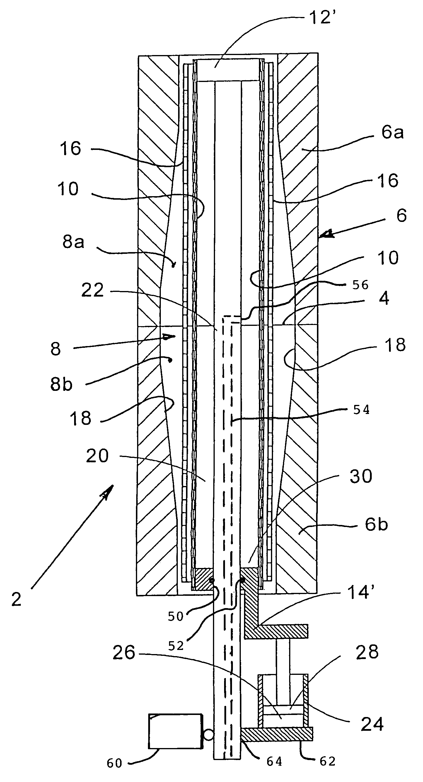
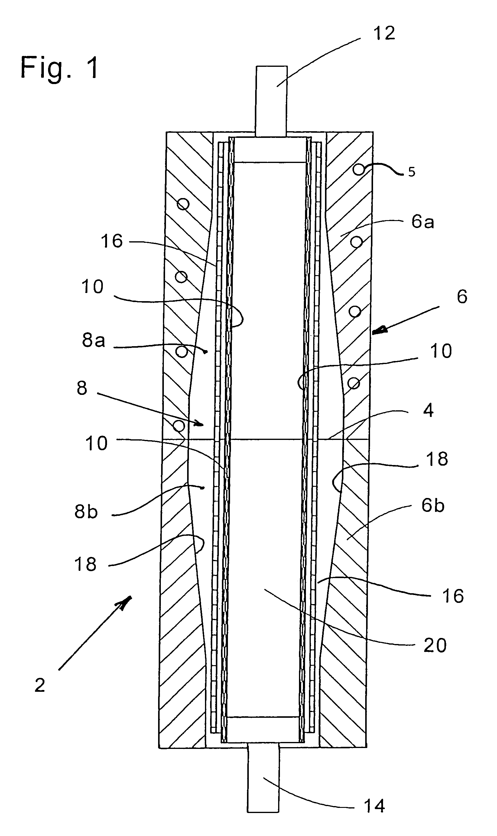
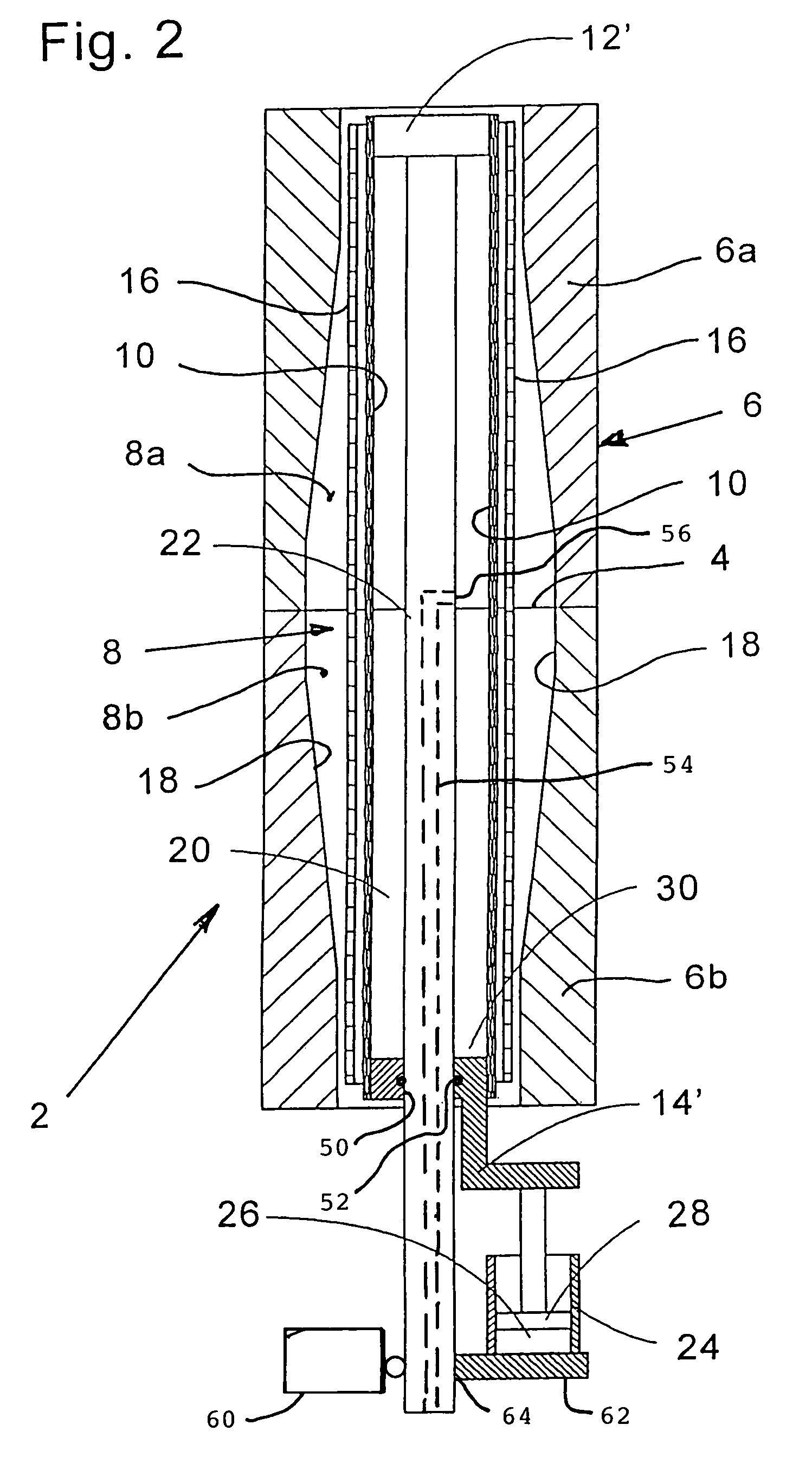
[0014]The apparatus 2 shown in FIG. 1 includes a two-part external double mold 6 which is axially partitioned at the partition plane 4. The external double mold 6 comprises an upper mold 6a as well as a lower mold 6b. The two halves or molds (6a, 6b) are heated, preferably electrically, as indicated schematically by heating coil 5 in mold 6a. Mold 6b is also equipped with a corresponding heating coil. Each of the halves (6a, 6b) includes an approximately bottle-shaped hollow space (8a, 8b) which are mirror images of each other so that a bellied expanse results in the center of the common hollow space 8.

[0015]A pressure bellows 10 extends axially in the interior of the double mold 6 and is made of a heat-resistant elastomeric material which is preferably additive cross-linked silicone. The ends of the pressure bellows are secured at their respective ends, for example, by clamping at the upper and lower end pieces (12, 14). The upper end piece 12 and the lower end piece 14 are axially...


PUM

PropertyMeasurementUnit
pressureaaaaaaaaaa
heataaaaaaaaaa
diametersaaaaaaaaaa

Abstract

Tubular-shaped flexible members for air springs are made of rubber or rubber-like elastomers and are reinforced by reinforcement layers. In order that the air spring flexible member can roll telescopically off a roll-off piston, the tubular-shaped flexible member sections must be brought into a slightly conical or bottle-like configuration and then vulcanized in this form. A method forms and vulcanizes an air spring flexible member blank and utilizes an apparatus which includes a mold defining a bellied inner wall defining a common hollow space for receiving the air spring flexible member blank therein. A pressure bellows unit includes a pressure bellows extending axially in the common hollow space as well as first and second end pieces joined to the pressure bellows at corresponding longitudinal ends thereof. In the method, the blank is placed over the pressure bellows and pressurized air is introduced into the interior of the pressure bellows to expand the pressure bellows thereby pressing the blank against the bellied inner wall and causing the pressure bellows to shorten. The end pieces are moved along the longitudinal axis to follow the shortening of the pressure bellows as the pressure bellows expands thereby holding a mechanical loading on the pressure bellows to a low value.

Description

CROSS REFERENCE TO RELATED APPLICATIONS[0001]This is a divisional application of application Ser. No. 10 / 682,577, filed Oct. 10, 2003, now U.S. Pat. No. 7,001,553 claiming priority from German patent application 102 47 337.4, filed Oct. 10, 2002, and incorporated herein by reference.FIELD OF THE INVENTION[0002]Air spring flexible members such as are used in the air springs of motor vehicles comprise rubber or rubber-like elastomers and are reinforced with reinforcement layers. The manufacture takes place at first in the form of a tube-shaped unvulcanized blank. In order that an air spring flexible member can roll off telescopically on a roll-off piston, the flexible member section must first be brought into a slightly conical or bottle-shaped form and then be vulcanized in this form. The invention relates to a method for forming and vulcanizing the tube-shaped flexible member blank. The invention also relates to an apparatus for forming and vulcanizing the tube-shaped flexible membe...

Claims


Application Information

Patent Timeline
Patent Type & Authority Patents(United States)
IPC IPC(8): B28B7/32B29C33/40B29C35/02F16F9/32B29C35/04B29C49/44B29C49/64B29D22/02
CPCB29C49/44B29D22/023B29C35/02B29C49/64Y10T156/1011B29K2019/00B29K2105/258B29C2049/0089B29C2949/08F16F9/32
Inventor BEDERNA, CHRISTOPHGAWINSKI, HUBERTUS
Owner CONTITECH LUFTFEDERSYST
Why Eureka
Try Eureka