Latch apparatus and method

a technology of latching and latching elements, applied in the direction of passenger lock actuation, carpet fasteners, lock applications, etc., can solve the problem that the control element does not impart motion (or sufficient motion) to the latch element or the latching mechanism for unlatching the door

Inactive Publication Date: 2008-04-29
STRATTEC SECURITY
View PDF107 Cites 38 Cited by
  • Summary
  • Abstract
  • Description
  • Claims
  • Application Information

AI Technical Summary

Benefits of technology

[0019]The present invention employs at least one control element movable in at least two different manners defining locked and unlocked states of the latch assembly. Movement of the control element in each manner is preferably defined by engagement and disengagement with another element. Specifically, the control element is movable in a first manner through a first path when engaged by the engagement element and is movable in a second manner through a second path when disengaged from the engagement element. Preferably, movement of the control element through the first path either directly or indirectly imparts motion to a latch element or mechanism (e.g., a ratchet). Such motion moves the latch element or mechanism to move to its unlatched position to unlatch the door. In contrast, when the control element moves through the second path, the control element does not impart motion (or sufficient motion) to the latch element or mechanism for unlatching the door. Therefore, whether movement or actuation of the control element by a user will unlatch the latch depends upon whether the control element moves in the first or the second manner. Preferably, the control element can be moved from the second path to the first path even if already partially or fully actuated through the second path (and preferably, vice versa). In highly preferred embodiments of the present invention, the control element can be moved from the first to the second path and from the second to the first path regardless of control element position in either path. Unlike conventional latch assemblies, this flexibility permits the state of the latch assembly to be changed even if an input to the latch assembly is already partially or fully actuated.

Problems solved by technology

In contrast, when the control element moves through the second path, the control element does not impart motion (or sufficient motion) to the latch element or mechanism for unlatching the door.

Method used


Image

  • Latch apparatus and method
  • Latch apparatus and method
  • Latch apparatus and method

Examples


third embodiment

[0170]By way of example only, one such alternative arrangement is illustrated in FIGS. 32-34. The latch assembly shown in FIGS. 32-34 is substantially the same as that shown in FIGS. 17-31, but with the exceptions described hereinafter. Reference numerals in this third embodiment are increased with respect to those in the second preferred embodiment to the 400 and 500 number series.

[0171]As can be seen in FIG. 32, the upper control element 452 and the lower control element 453 are each connected to the pawl 454 by a respective link 556, 558. The links 556, 558 can take virtually any shape and can be connected to the control elements 452, 453 and to the pawl 454 in any conventional manner which allows relative movement of the control elements 452, 453 and the pawl 454 (i.e., by welding, brazing, gluing, fastening with fasteners, and the like). Preferably however, the links 556, 558 are U-shaped wires or rods bent to fit within suitably sized apertures in the control elements 452, 453...

fourth embodiment

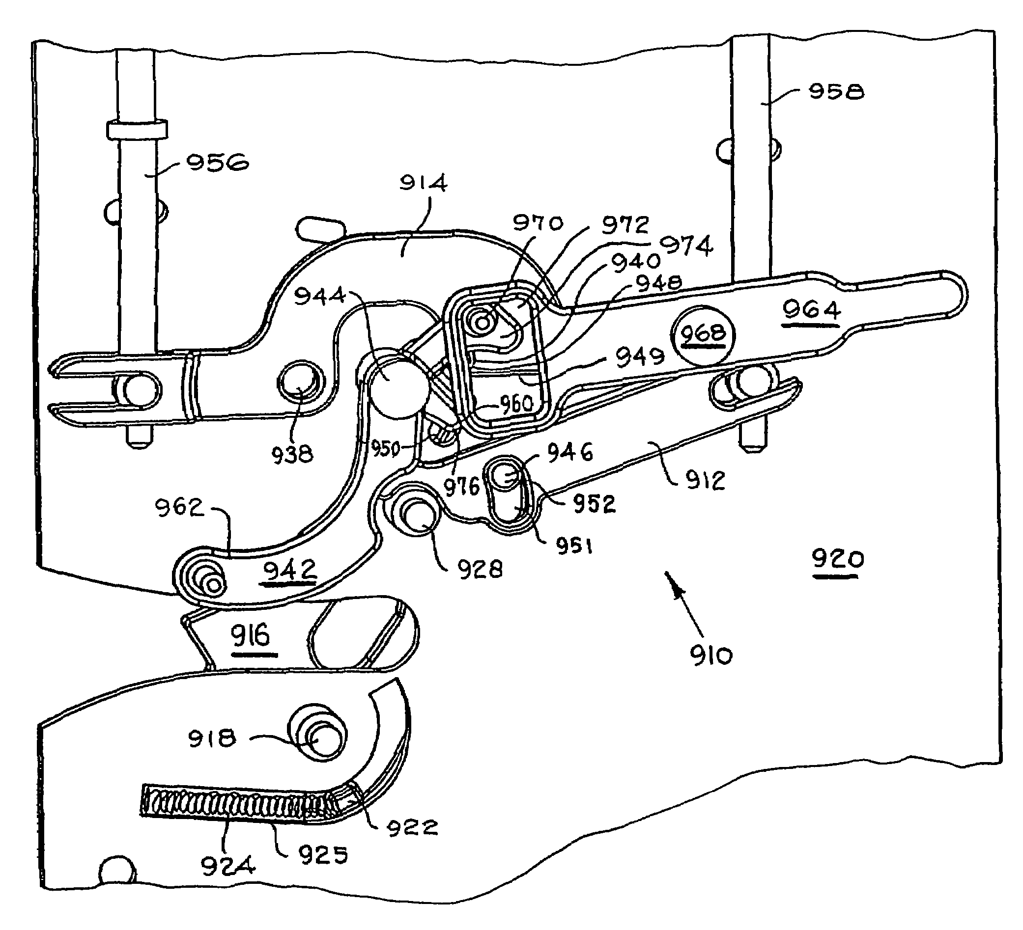
[0221]Like the other embodiments of the present invention described earlier, the present invention preferably employs one or more springs and stop elements to place the various elements in the latch assembly in desired at-rest positions. Preferably, the upper control element 652 has two at-rest positions defined by at least one spring 772 and at least one stop 774. These two at-rest positions are preferably the locked and unlocked positions of the upper control element 652 shown in FIGS. 41 and 42, respectively. The spring 772 is preferably connected to one of the guidance posts 743 in any conventional manner and extends to a position alongside the path of the upper control element lever end 664. When the upper control element 652 is fully actuated by the linking element 730 to unlock the latch assembly 610, the upper control element 652 preferably moves past an elbow 780 in the spring 772. This elbow 780 provides some degree of force upon the upper control element 652 to bias the u...

embodiment 610

[0249]For purposes of illustration, operation of a preferred embodiment of the actuator 800 will now be described with reference to its application in the fourth preferred latch assembly embodiment 610. It should first be noted, however, that the latch assembly 610 described above need not employ this type of actuator. In this case, the lower actuator 688 is preferably a two-stage actuator 800 as described above (although either or both actuators 668, 688 could be such an actuator in alternative embodiments). Specifically, the lower control element 653 is the element to be controlled 816, the lower pin 686 is the pin 812 of the actuator 800, and the lower pin plate 706 is the body of the holding element 808. The track 818, within which the lower pin plate 706 is movable, is shown as a groove in the interior wall of the front cover 612, and has a width sized to slidably receive the edges of the lower pin plate 706. As such, the lower pin plate 706 is movable through the track 818 in ...


PUM


Abstract

A latch assembly having at least one control element having a first path of motion in which a ratchet is moved to an unlatched position and a second path of motion in which the ratchet is not so moved, the path of motion taken by the control element dependent upon whether an engagement element is engaged with the control element or disengaged therefrom. Preferably, the control element moves the ratchet by contact with a pawl which itself can be engaged with the ratchet. In a preferred embodiment of the present invention, the control element can be partially or fully actuated through its second path of motion while still being engagable with its engagement element. If already partially or fully actuated through its second path of motion, the engagement element is preferably movable into contact with the control element and can move the control element to its first path of motion. The latch assembly can have a second control element also having first and second paths of motion determined at least partially upon whether an engagement element is engaged with the second control element or disengaged therefrom. The second control element can be connected to the first engagement element to move the first engagement element into and out of engagement with the first control element when the second control element is actuated in its engaged state.

Description

[0001]This patent application is a continuation of prior application Ser. No. 09 / 571,340, filed on May 16, 2000, now U.S. Pat. No. 6,786,070, which is a continuation-in-part of application Ser. No. 09 / 522,158, filed on Mar. 9, 2000, now U.S. Pat. No. 6,705,140, which is a continuation-in-part of application Ser. No. 09 / 408,993, filed on Sep. 29, 1999, now abandoned, which is a continuation-in-part of application Ser. No. 09 / 263,415, filed on Mar. 5, 1999, now U.S. Pat. No. 6,463,773. The entire disclosures of the prior applications are incorporated herein by reference.FIELD OF THE INVENTION[0002]The present invention relates to latches and latching methods, and more particularly to devices and methods for controlling and switching a latch between latched and unlatched states.BACKGROUND OF THE INVENTION[0003]Conventional latches are used to restrain the movement of one member or element with respect to another. For example, conventional door latches restrain the movement of a door wi...

Claims


Application Information

Patent Timeline
Patent Type & Authority Patents(United States)
IPC IPC(8): E05B47/00E05B51/02E05B53/00E05B63/00E05B65/12E05B65/20
CPCE05B77/30E05B81/06E05B81/08E05B81/16E05B81/10E05B79/20E05B83/36E05B47/0009E05B63/0056E05B77/26E05B81/90E05B77/28Y10S292/27Y10T70/5805Y10T292/1047Y10T70/7062Y10T292/1082Y10T70/7102
Inventor DIMIG, STEVEN J.EDGAR, JAMES
Owner STRATTEC SECURITY
Why Eureka
Try Eureka