Speed regulator with distance regulating function

a technology of distance regulation and speed controller, which is applied in the direction of process and machine control, using reradiation, instruments, etc., can solve the problems of significant decrease in comfort or nuisance of traffic behind, increase the danger of obstruction not being detected and recognized, and limited detection range of radar systems, so as to increase the comfort of the driver, increase the effect of traffic safety and limit the promp

Inactive Publication Date: 2008-05-13
ROBERT BOSCH GMBH
View PDF21 Cites 39 Cited by
  • Summary
  • Abstract
  • Description
  • Claims
  • Application Information

AI Technical Summary

Benefits of technology

[0007]The present invention facilitates, in the cases in which reduction in speed to very low speeds or, if necessary, to a standstill, occurs during operation of the speed controller, a safe and reliable distance regulation up to the point the vehicle comes to a standstill in spite of the gaps within the detection range of the locating system. In most cases, the external vehicle that is selected as the target object for distance regulation will remain within the detection range until both vehicles have decelerated to a standstill. In these cases, there is no need, even when the speed falls below the previously set limiting speed, for the speed controller to be shut off and the driver to be prompted to manually take over. Special precautionary measures are necessary for the cases in which the tracked target object “disappears” from the detection range during reduction in speed and the associated reduction in distance because, for example, the two vehicles in the same traffic lane are moving in such a way that they are offset laterally from one another by a relatively great distance so that the vehicle ahead ends up in the blind spot of the radar system as the distance decreases. However, these situations that require a takeover prompt to the driver may be identified with a high degree of certainty based on prior history, i.e., based on the locating data measured immediately before the loss of the target object. It is therefore possible to limit the takeover prompt to these special cases.
[0008]The resulting expansion of the range of application of the speed controller results not only in a considerable increase in comfort for the driver, but it also contributes to an increase in traffic safety since the driver is relieved of distraction when driving up to the back end of a traffic jam and is thus able to pay more attention to what is happening in the adjacent lanes, so that, for example, he is able to recognize earlier when a driver of a vehicle in the adjacent lane is planning to change lanes and move into the safe interval between the vehicle and the vehicle ahead.
[0009]By avoiding unnecessary takeover prompts, the danger is also reduced that, in the event of a takeover prompt of this kind, the driver will irritate the traffic behind him through an overreaction such as sudden and excessive braking. By continuing automatic regulation even at very low speeds, it is also possible in this speed range to take full advantage of the fact that the locating system is able to detect changes in the distance and relative speed of the vehicle ahead significantly more accurately and earlier than the driver himself can, so that a faster and more appropriate reaction to changes in the deceleration or acceleration behavior of the vehicle ahead becomes possible.
[0010]ACC systems may be supplemented by what has been referred to as a “stop & go” or “stop & roll” function, by which, in the event of a traffic jam or slow-moving traffic, not only automatic braking to a standstill, but also starting up again and slow rolling in the traffic jam is automated. In conjunction with these functions, which may also be used in inner-city traffic, for example, the speed controller according to the present invention also proves to be particularly advantageous.
[0011]In an ACC system, or even in conjunction with the stop & go function, takeover prompts to the driver in the form of an acoustic and / or optical signal may also occur in other situations. In an ACC system, the amount of vehicle deceleration that is achievable through automatic intervention in the drive system or braking system of the vehicle is normally limited to values that do not result in a significant decrease in comfort or decrease in nuisance to the traffic behind it. If the system recognizes that the deceleration that is attainable in this way is not sufficient to avoid a collision with the vehicle ahead, then a takeover prompt is issued at that point, even in known systems. In the present invention, the takeover prompt has the same form as in these known systems so that the driver is not irritated by a variety of unfamiliar signals but, instead, is faced with a harmonized, easy-to-interpret and familiar man-machine interface.

Problems solved by technology

The reason for this shutoff is primarily that the detection range of the locating system has gaps in the close range so that, as the distances from the target objects decrease, the danger increases that an obstruction will not be detected and recognized, even if it is in the same traffic lane.
For example, the detection range in radar systems is limited by the geometry of the radar beam, which emanates divergently from the radar sensor and scans only a limited angle range so that the full width of the traffic lane is not detected until a certain distance in front of the vehicle is reached.
In an ACC system, the amount of vehicle deceleration that is achievable through automatic intervention in the drive system or braking system of the vehicle is normally limited to values that do not result in a significant decrease in comfort or decrease in nuisance to the traffic behind it.
For example, the loss of the target object may simply be due to the fact that the vehicle immediately ahead has changed lanes.
The danger that a target object will disappear from the detection range even though it remains in the vehicle's traffic lane is particularly great when traveling along a curve.
If the target object is located on the outer edge of the detection range relative to the curve, in particular, it is to be expected that this target object will be lost when the distance from the target object is further reduced and / or when the vehicles exit again from the curve.
In general, the tighter the traveled curve is, the larger the close-range portion of the vehicle's traffic lane becomes that can no longer be detected by the locating system.

Method used


Image

  • Speed regulator with distance regulating function
  • Speed regulator with distance regulating function
  • Speed regulator with distance regulating function

Examples


Embodiment Construction

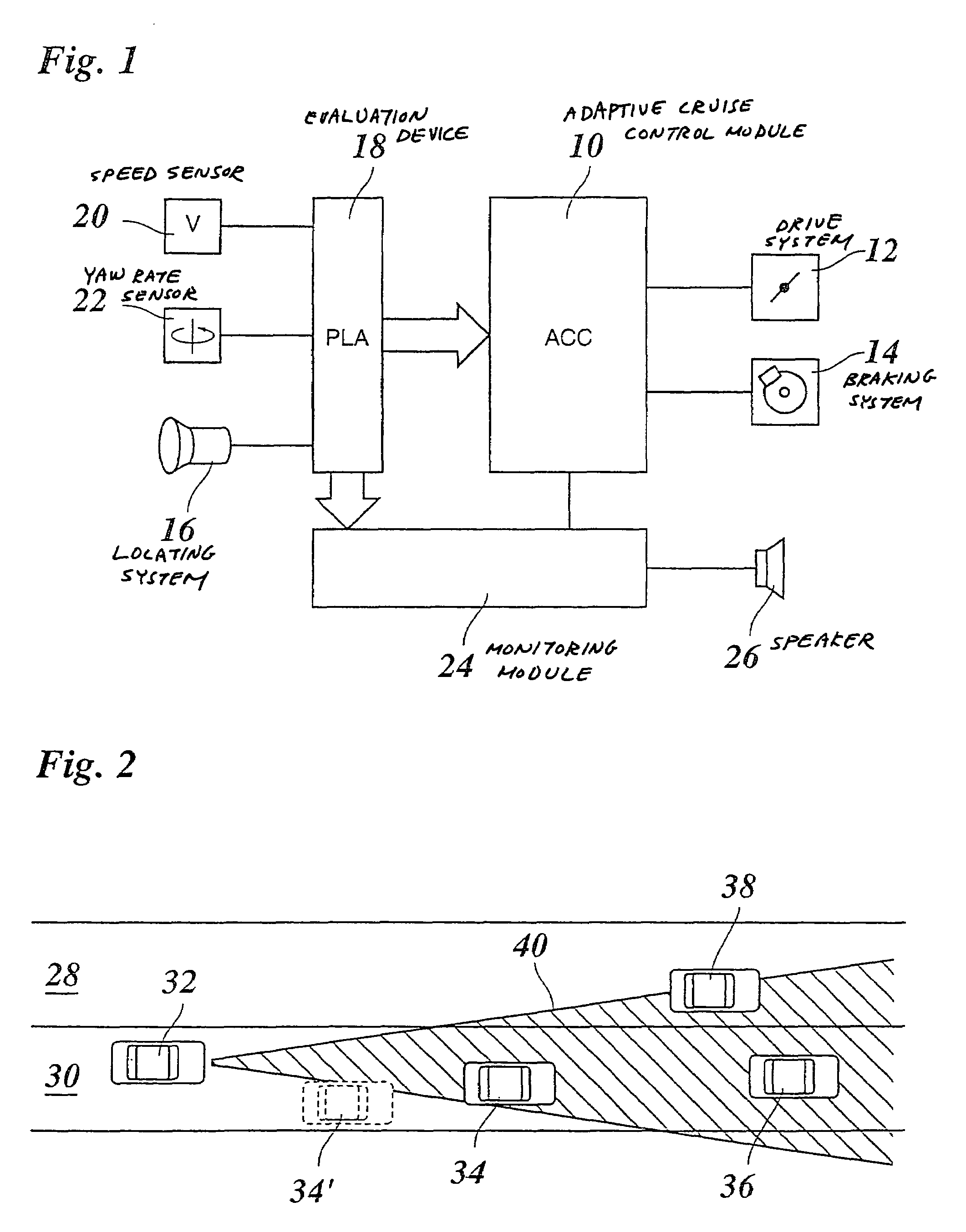
[0023]Since the basic design and mode of operation of a speed controller or an ACC (adaptive cruise control) system for motor vehicles are known, FIG. 1 shows only the most important components of a system of this type in a simplified block diagram. The heart of the system is an ACC module 10 that intervenes in the motor vehicle's drive system 12 and braking system 14 and, if the road is clear, regulates the driving speed to the desired speed set by the driver. A locating system 16, in the form of a direction-selective multibeam radar mounted on the front of the vehicle in the example shown, measures the distances and relative speeds of the vehicles ahead and also the stationary targets that are within the detection range of the radar. The locating system 16 also measures the azimuth angle of the detected objects relative to the current straight-line direction of the vehicle. The locating data measured by locating system 16 for all detected objects is transmitted to an evaluation de...


PUM


Abstract

A speed controller for motor vehicles is provided, the vehicle having a distance regulating function, a locating system for detecting locating data for objects that are in front of the vehicle, and an evaluation device for determining whether a located object needs to be treated as a relevant target object in the vehicle's lane. The speed controller includes a monitoring module that is designed to detect, by reference to the locating data, a situation in which objects not detected by the locating system are within close range and, in this situation, issue a takeover prompt to the driver.

Description

FIELD OF THE INVENTION[0001]The present invention relates to a speed controller for motor vehicles that includes a distance-regulating function, a locating system for detecting locating data for objects that are in front of the vehicle, and an evaluation device for determining whether a located object needs to be treated as a relevant target object in the vehicle's traffic lane.BACKGROUND INFORMATION[0002]Distance and speed controllers for motor vehicles are known in the art and are also referred to as ACC (“adaptive cruise control”) systems. In these systems, objects such as vehicles ahead that are in the same traffic lane in which the controlled vehicle is traveling are detected using a locating system. The locating system can be a camera system or a radar system, using which the distance to the vehicle ahead and the relative speed can be measured. By using a direction-sensitive radar system or by relying on additional parameters such as the steering angle of the vehicle, the dete...

Claims


Application Information

Patent Timeline
Patent Type & Authority Patents(United States)
IPC IPC(8): B60T7/12B60W10/04B60K31/00B60T7/22B60W30/16B60W50/08F02D29/02G01S13/931G08G1/16
CPCB60K31/0008B60T7/22B60W30/16G01S13/931B60W2050/143B60W2550/143B60W2550/304G01S2013/9325B60W2550/308G01S2013/935G01S2013/9353G01S2013/9357G01S2013/9321B60W2550/306G01S2013/9319G01S2013/9322G01S2013/932B60W2554/803B60W2552/20B60W2554/4041B60W2554/801B60W2552/30B60W2554/4043B60W30/18145
Inventor WAGNER, KLAUS-PETERWINNER, HERMANN
Owner ROBERT BOSCH GMBH
Why Eureka
Try Eureka