Image forming apparatus and method

a technology of image forming and forming apparatus, which is applied in the direction of printing, other printing apparatus, etc., can solve the problems of not being able to achieve high-speed printing and high-quality printing, and achieve the effect of high-quality

Inactive Publication Date: 2008-05-20
FUJIFILM CORP
View PDF4 Cites 18 Cited by
  • Summary
  • Abstract
  • Description
  • Claims
  • Application Information

AI Technical Summary

Benefits of technology

[0007]The present invention has been contrived in view of the foregoing circumstances, an object thereof being to provide an image forming apparatus and method whereby optimal droplet ejection interval control which is suitable for both high-speed printing and high-quality printing can be achieved, by determining various conditions under which landing interference will not occur, when radiation-curable ink droplets are ejected in a mutually overlapping fashion.

Problems solved by technology

However, in ultraviolet-curable inks, it is rare for the viscosity to pass through a semi-solidified state and for the ink to then solidify, due to irradiation of radiation, and in most cases, the ink changes directly from a liquid state to a solid state.
In Japanese Patent Application Publication No. 2004-42548, there is no disclosure regarding optimal droplet deposition timing which takes account of the aforementioned point, and it is not possible to achieve both high-speed printing and high-quality printing.

Method used


Image

  • Image forming apparatus and method
  • Image forming apparatus and method
  • Image forming apparatus and method

Examples


Embodiment Construction

Description of Curing Process for Ultraviolet-Curable Ink

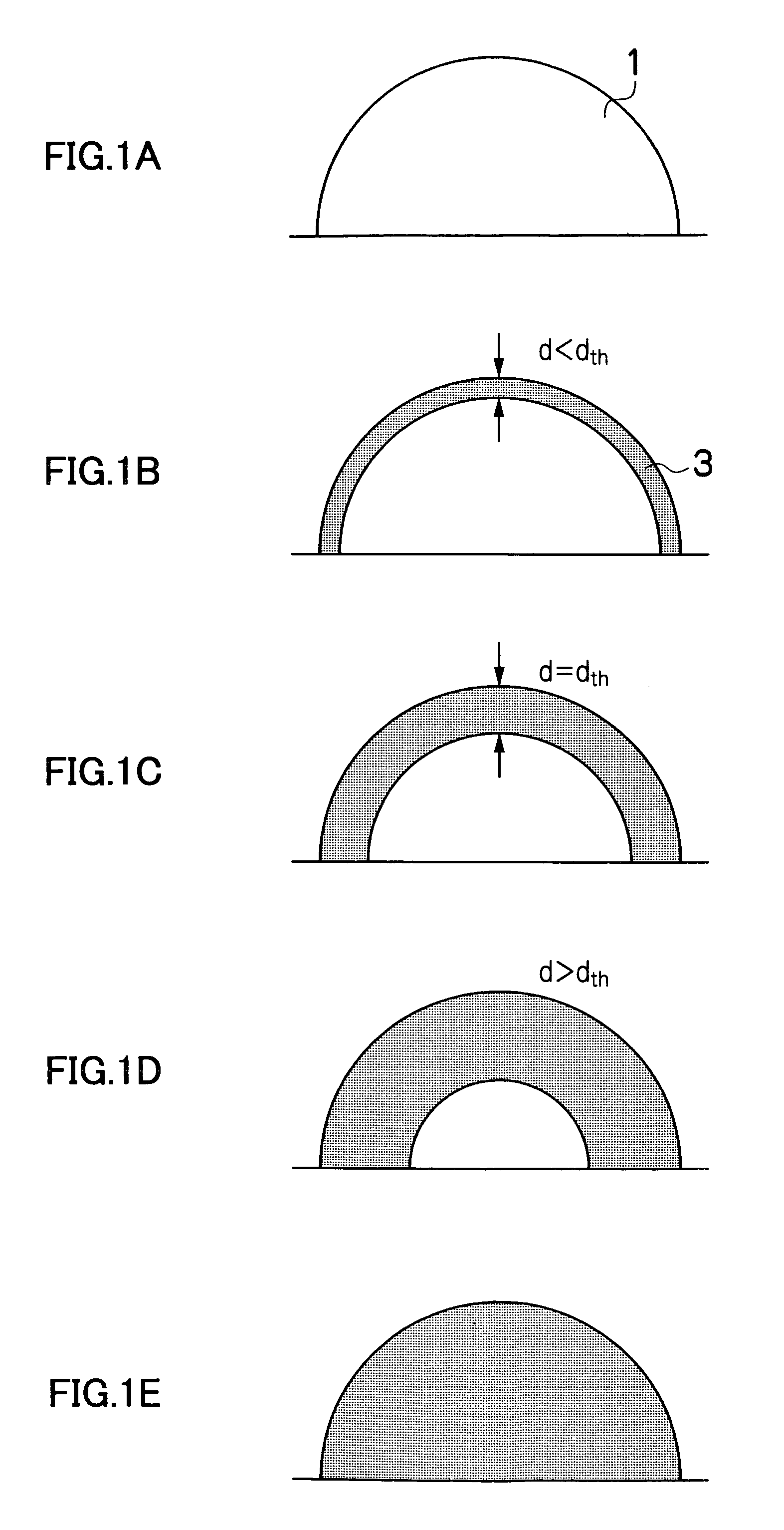
[0047]FIGS. 1A to 1E are schematic drawings showing the gradual progression, with the passage of time, of a curing reaction which progresses from the surface of the liquid toward the inner side as ultraviolet light is irradiated onto a droplet of ultraviolet-curable ink after it has been deposited on a recording medium. In FIGS. 1A to 1E, for the sake of convenience, the deposited liquid droplet is shown as having a hemispherical shape, but an actual liquid droplet will have a flatter shape than that shown in the drawings.

[0048]FIG. 1A shows a state immediately after the ultraviolet-curable ink droplet has landed on the recording medium. In this case, the whole of the ink droplet 1 is still in a liquid state. FIG. 1B shows a state where ultraviolet light has been irradiated onto the ink droplet and the region of the outermost surface of the ink droplet has undergone a curing reaction. In this state, the film thickness d of the...


PUM


Abstract

The image forming apparatus comprises: an ink ejection device which ejects droplets of a radiation-curable ink onto a recording medium; a conveyance device which causes the ink ejection device and the recording medium to move relatively to each other in a relative movement direction by conveying at least one of the ink ejection device and the recording medium; a radiation irradiation device which irradiates radiation to the droplets deposited on the recording medium by the ink ejection device; a dot formation conditions determination device which determines a dot size of dots and a pitch between adjacent dots to be formed by the ejected droplets, according to print data; and a droplet ejection timing control device which sets an ejection interval between the droplets according to information relating to the dot size and the dot pitch determined by the dot formation conditions determination device, and controls an ejection timing of a subsequent droplet ejected subsequently in an overlapping fashion, in such a manner that the subsequent droplet is ejected to form a dot overlapping with a dot formed by a droplet deposited previously on the recording medium, after a surface of the previously deposited droplet is preliminarily cured to a threshold cured film thickness by the radiation.

Description

BACKGROUND OF THE INVENTION[0001]1. Field of the Invention[0002]The present invention relates to an image forming apparatus and method, and more particularly, to an image forming apparatus and method for forming images on a recording medium by using a radiation-curable ink which is cured by irradiation of radiation such as ultraviolet light or the like.[0003]2. Description of the Related Art[0004]Technology using ultraviolet-curable ink (so-called UV ink) in an inkjet type image forming apparatus is known. Japanese Patent Application Publication No. 2004-42548 discloses technology for preventing the occurrence of mottling and bleeding, in cases where dots are recorded by depositing droplets of ultraviolet-curable ink from different nozzles, at prescribed staggered time intervals, by irradiating ultraviolet light in conjunction with the deposition timing of the respective droplets, thereby pre-curing mutually adjacent droplets to a degree which prevents them from mixing together, and...

Claims


Application Information

Patent Timeline
Patent Type & Authority Patents(United States)
IPC IPC(8): B41J2/01
CPCB41J11/002B41J11/00214B41J11/00212B41J11/00218B41J2/2146B41J2/2135
Inventor KUSUNOKI, NAOKI
Owner FUJIFILM CORP
Why Eureka
Try Eureka