
Method for generating a dither mask

a mask and mask technology, applied in the field of halftoneing, can solve the problems of worm artifacts at low grey scale levels, visible artifacts or textures in printed images, error diffusion techniques,

Inactive Publication Date: 2005-12-29
OCE TECH
View PDF8 Cites 4 Cited by
  • Summary
  • Abstract
  • Description
  • Claims
  • Application Information

AI Technical Summary

Benefits of technology

"The invention provides a method and computer program for generating dither masks using a stochastic technique for halftoning grey scale images. The dither masks should avoid or limit undesired textures in printed images, especially when the images are printed with different resolutions along the print medium. The method involves generating a sequence of dot profiles, each corresponding to a grey scale level, using a stacking constraint with an incremental grey scale level. The position of each additional pixel is determined dependent on the positions of previously selected pixels using the local stochastic technique taking account of the aspect ratio between the dot pitch in a predetermined direction and a direction perpendicular thereto when rendering images. The invention overcomes limitations and problems associated with background art and provides a method with limited processing time and resources."

Problems solved by technology

This may lead to visible artifacts or textures in the printed image.
Error diffusion techniques are however known to create worm artifacts at low grey scale levels and to require high processing resources.
A potential disadvantage of using non-stochastic dithering masks is that highly structured image dot patterns may be produced which are highly susceptible to positioning errors and hence may introduce banding effects.
A problem associated with the aforementioned examples is that this global stochastic approach for generating dither matrices is complex and time consuming and requires very large processing resources.
The fact that stochastic dither masks are not designed to cope with a difference in resolution in both print directions leads to undesired and perceptually disturbing snake-like textures in the printed image in the direction having the higher printer resolution.

Method used


Image

  • Method for generating a dither mask
  • Method for generating a dither mask
  • Method for generating a dither mask

Examples


example

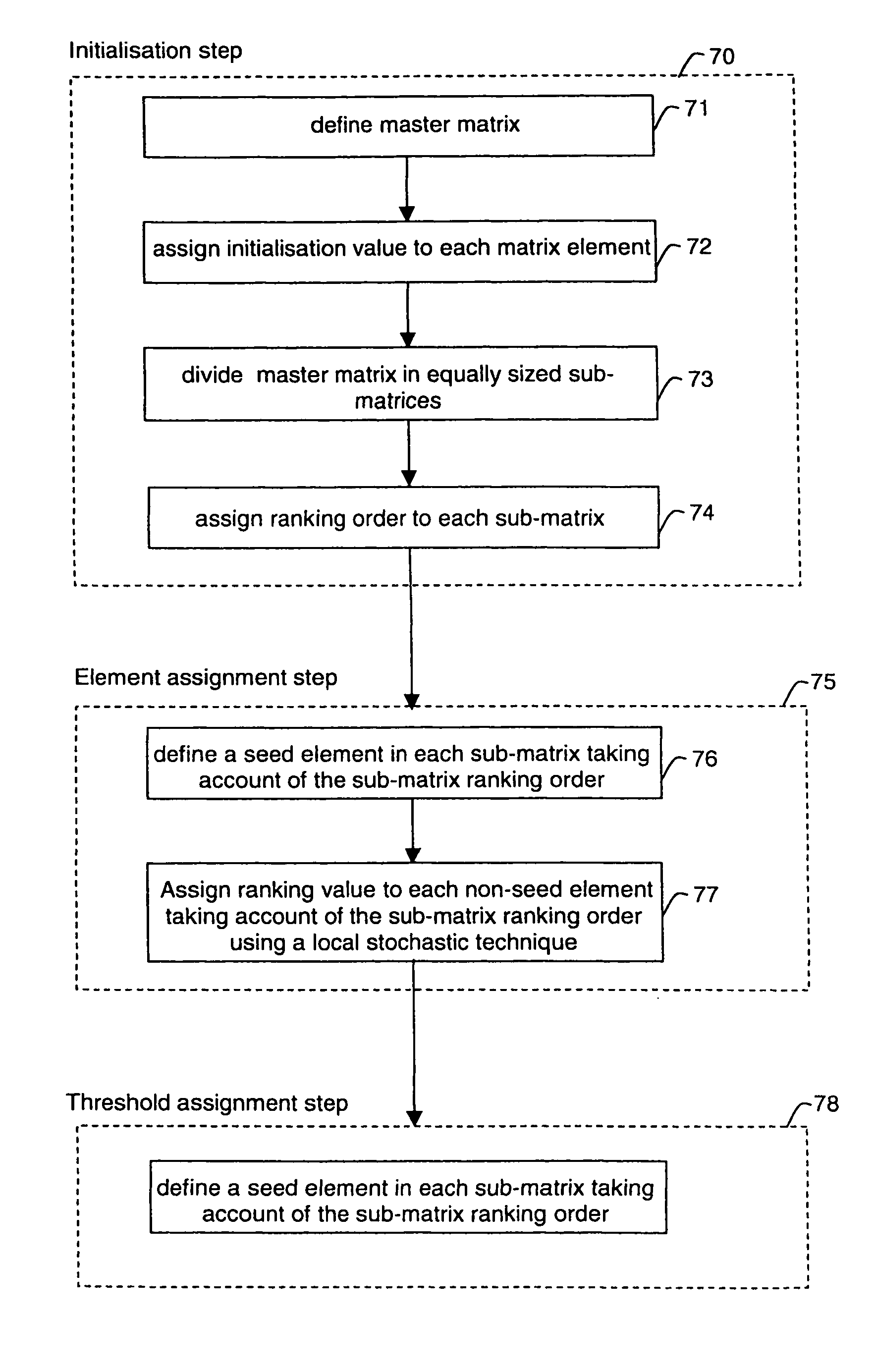
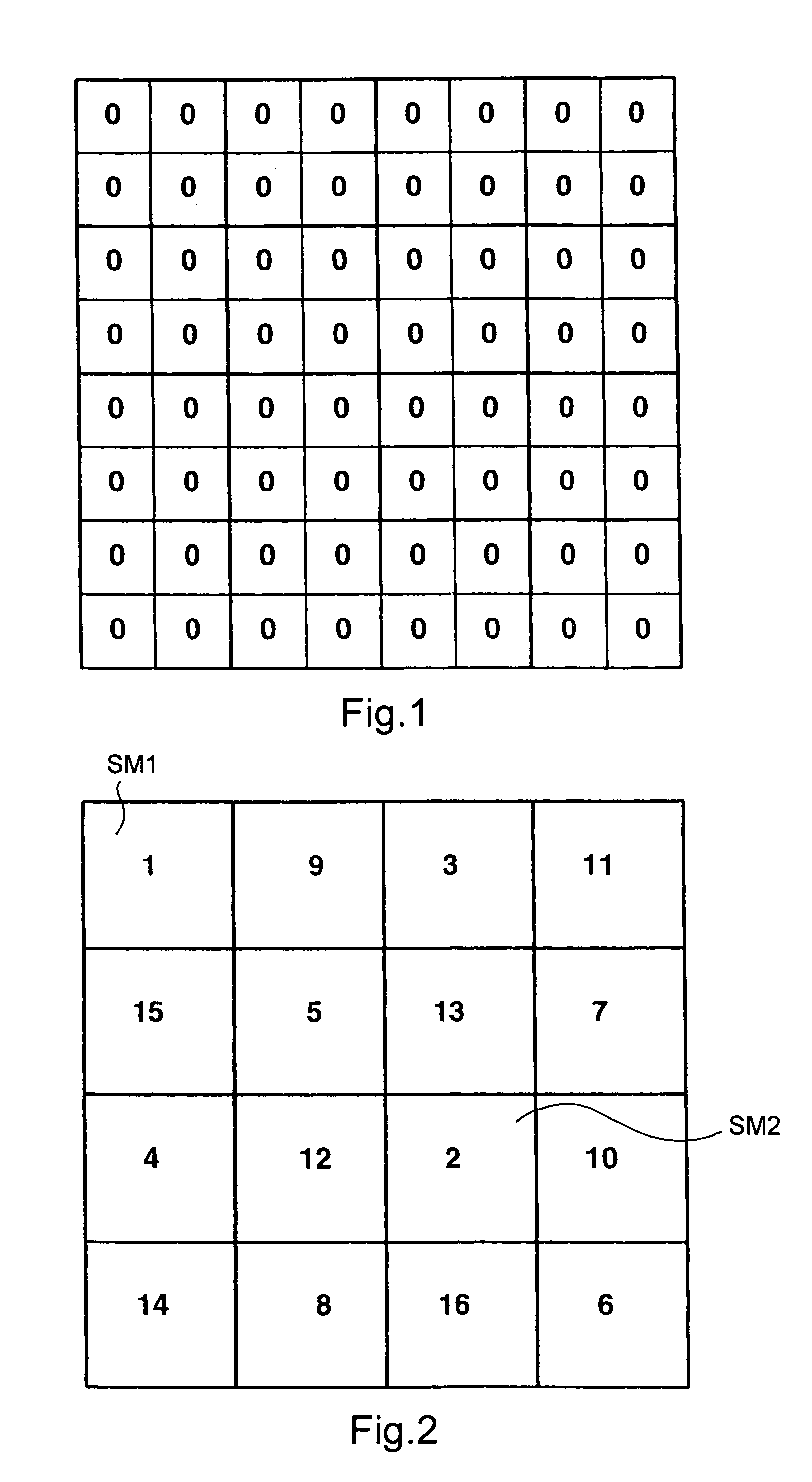
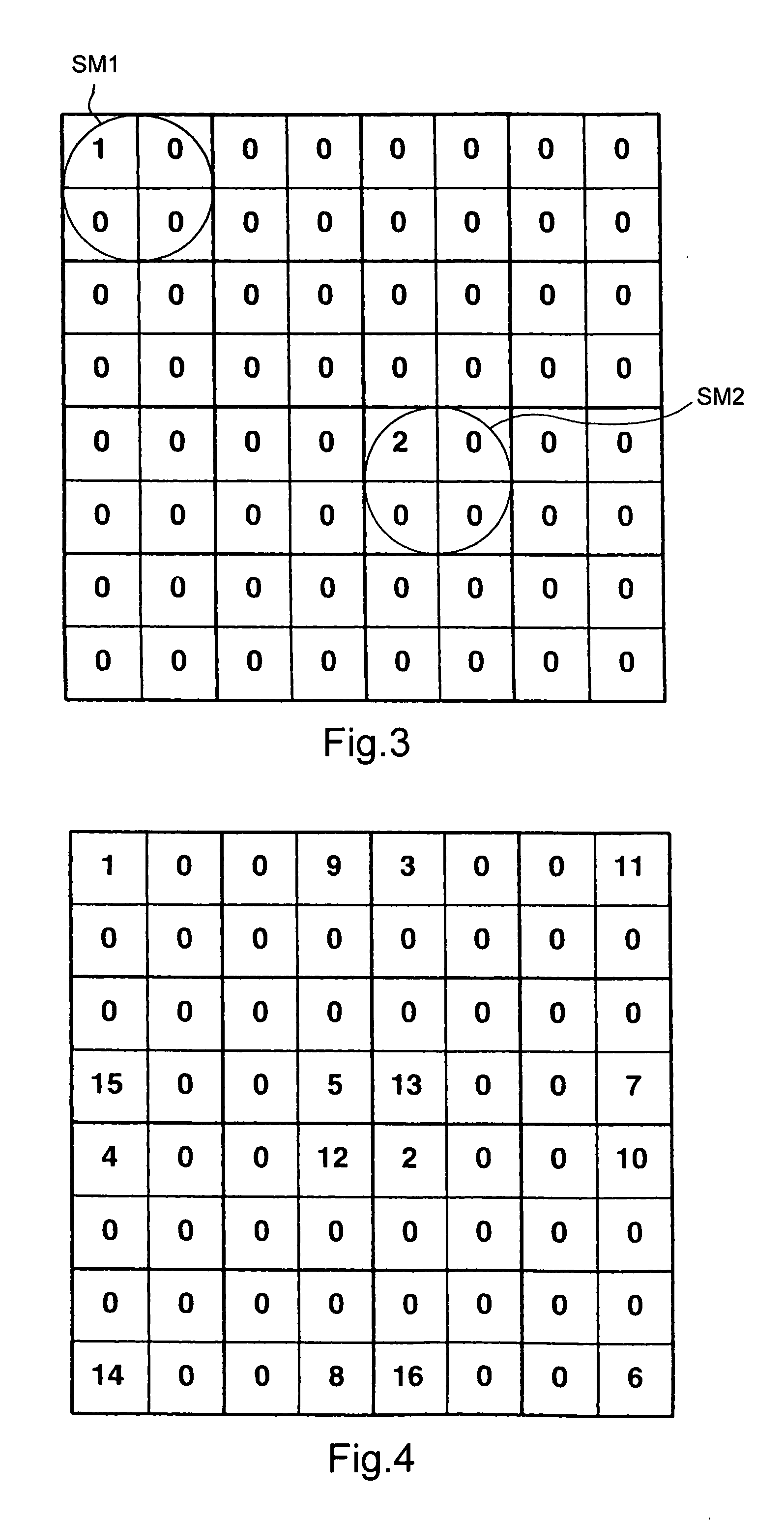
[0034] Assume that a dither mask is to be generated for use for the halftoning of a grey scale image having only 4 grey scale levels. In practice this is usually at least 256. The master matrix should have a number of elements being an integer plurality of the number of grey scale levels, the integer value being at least two. Assume that this integer value is chosen to be 16, thus defining an 8×8 master matrix having 64 matrix elements. As demonstrated in FIG. 1, an initialization value being zero is assigned to each element of the master matrix. The master matrix is divided in 16 equally sized 2×2 sub-matrices. Hence each sub-matrix includes four elements, being as many elements as the number of grey scale levels of the separation image. As demonstrated in FIG. 2, the sub-matrices are ranked by assigning an incremental integer value to each of the sub-matrices, starting with the integer value one and ending with the integer value 16. Subsequently, the initialization value of each e...


PUM


Abstract

A method for generating a dither mask is disclosed using a local stochastic technique for use for the halftoning of grey scale images by a pixel by pixel comparison of the images against the dither mask. The dither mask is generated by producing a sequence of dot profiles (each dot profile of the sequence corresponding to a grey scale level) using a stacking constraint with incremental grey scale level such that for each dot profile of the sequence the same pixels are selected compared to the preceding dot profile and the increment in the or each dot profile is realized by selecting at least one additional pixel. When determining the position of an additional pixel, the aspect ratio between the dot pitch in a predetermined direction and a direction perpendicular thereto when rendering images is taken into account.

Description

[0001] This application claims the benefit of the European Patent Application No. 04076720.4 filed on Jun. 14, 2004, which is hereby incorporated by reference. FIELD OF THE INVENTION [0002] The present invention is related to the halftoning of continuous tone or grey scale images for reproduction on a printing or copying system. Particularly of interest are methods for generating a dither mask for use for the halftoning of grey scale images. BACKGROUND OF THE INVENTION [0003] Halftoning is a conversion technique enabling to render continuous tone images or grey scale images on printing devices having a lower tonal resolution. In case of a bi-tonal device, continuous tone information is simulated by controlling the coverage or in other words the amount of pixels in a multi pixel area which are actually rendered as image dots. There is a trade off between spatial resolution and tonal resolution. As a result of the halftoning method, image dots are formed in certain ordered patterns. T...

Claims


Application Information

Patent Timeline
Patent Type & Authority Applications(United States)
IPC IPC(8): H04N1/405
CPCH04N1/4051
Inventor KUIPER, PAUL
Owner OCE TECH
Learn More