Sphere stationing method, capture ball and system for optical motion capture

An optical motion, sphere technology, applied in the direction of instruments, character and pattern recognition, computer parts, etc., can solve the problems that affect the real-time motion gesture recognition and trajectory tracking effect of the capture ball, the poor motion gesture recognition effect, and affect the capture process, etc. Achieve the effect of enhancing real-time gesture recognition, ensuring stability, and improving calculation speed

Active Publication Date: 2018-11-16
SHENZHEN REALIS MULTIMEDIA TECH CO LTD
View PDF8 Cites 3 Cited by
  • Summary
  • Abstract
  • Description
  • Claims
  • Application Information

AI Technical Summary

Problems solved by technology

[0004] (1) When recognizing the catching ball in the form of a rigid body, since there are a lot of reflective stickers on the catching ball to configure a large number of reflective marks, in order to fully recognize the motion posture of the catching ball, in the later stage of posture recognition and trajectory tracking process , to traverse the three-dimensional coordinates of each reflective mark, the calculation is huge, which will greatly affect the real-time motion gesture recognition and trajectory tracking effect of the catching ball
[0005] (2) The structure of the catching ball has a difference in size. A ball with a relatively large diameter will cause unpredictable occlusion of the reflective sticker during motion, which will affect the capture process and bring poor motion gesture recognition effect.

Method used


Image

  • Sphere stationing method, capture ball and system for optical motion capture
  • Sphere stationing method, capture ball and system for optical motion capture
  • Sphere stationing method, capture ball and system for optical motion capture

Examples


Embodiment Construction

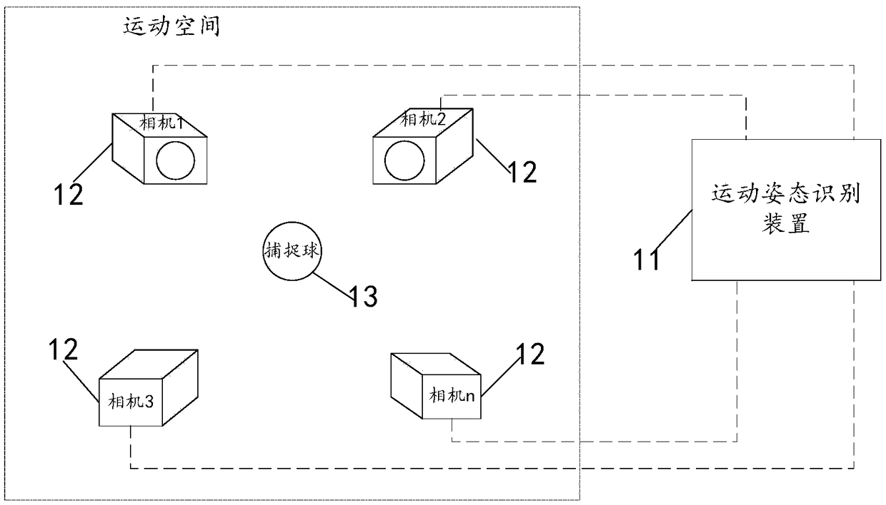
[0037] The present invention will be further described in detail below through specific embodiments in conjunction with the accompanying drawings. Wherein, similar elements in different implementations adopt associated similar element numbers. In the following implementation manners, many details are described for better understanding of the present application. However, those skilled in the art can readily recognize that some of the features can be omitted in different situations, or can be replaced by other elements, materials, and methods. In some cases, some operations related to the application are not shown or described in the description, this is to avoid the core part of the application being overwhelmed by too many descriptions, and for those skilled in the art, it is necessary to describe these operations in detail Relevant operations are not necessary, and they can fully understand the relevant operations according to the description in the specification and genera...


PUM


Abstract

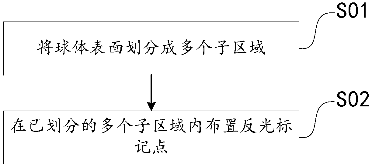
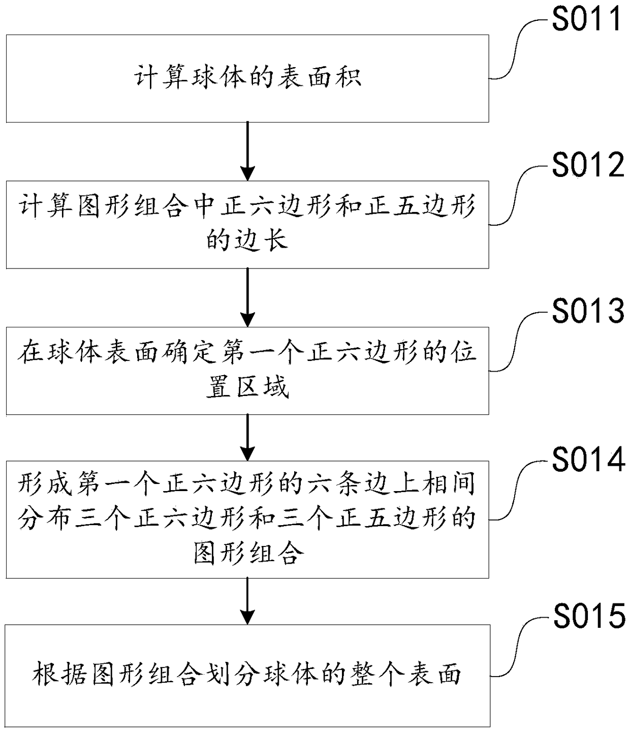
The present invention provides a sphere stationing method, a capture ball and a system for optical motion capture. A pre-determined graph combination is employed to divide the surface of a sphere to allow the surface of the sphere to show a uniform graph distribution state and facilitate setting of reflective marking points of the sphere at the vertex of each geometry image or edge central point of each geometry image so as to form a capture ball for optical capture. The capture ball obtained by employing the sphere stationing method is uniform in stationing and small in distance difference between the reflective marking points to facilitate rapid capture of the reflective marking points on the capture ball through the system and facilitate obtaining of the motion pose information of the capture ball by the system according to the displacement change recognition of the reflective marking points when the optical capture system is utilized to perform motion pose recognition of the capture ball. The sphere stationing mode is employed to obtain the capture ball, the motion pose recognition of the capture ball can be performed in a condition that there are only few matching points on the sphere, and therefore, the system computing amount is reduced, and convenience is brought to the practical application.

Description

technical field [0001] The invention relates to the technical field of optical motion capture, in particular to a method for arranging spheres for optical motion capture, a catching ball and a system. Background technique [0002] In the existing optical motion capture system, generally by capturing the movement track of reflective markers (markers, which refer to markers covered with special reflective materials on the surface, common shapes are spherical and hemispherical, etc., are often used to capture moving objects) In order to realize the motion posture recognition and trajectory tracking of the target object. Usually, a plurality of reflective marks configured on the capture object will form a rigid body that can be captured (the rigid body here refers to the shape and size of the rigid body during motion and after the force is applied, and the relative position of the internal points An unchanging object is an ideal model), and each reflective mark corresponds to a...

Claims


Application Information

Patent Timeline
Patent Type & Authority Applications(China)
IPC IPC(8): G06K9/00
CPCG06V40/20
Inventor 王越长坂友裕许秋子
Owner SHENZHEN REALIS MULTIMEDIA TECH CO LTD
Why Eureka
Try Eureka