LED screen correction image acquisition method, correction method, acquisition device and correction system

A technology for correcting images and LED screens, applied to instruments, static indicators, etc., can solve problems such as peripheral out-of-focus, inaccurate data, and impact on collection efficiency, so as to solve peripheral out-of-focus and distortion, ensure the correction effect, and improve the image The effect of collection efficiency

Active Publication Date: 2021-08-13
SHENZHEN LIDING PHOTOELECTRIC TECH
View PDF6 Cites 4 Cited by
  • Summary
  • Abstract
  • Description
  • Claims
  • Application Information

AI Technical Summary

Problems solved by technology

[0003] However, since each lens has its own optimal magnification range, if the actual magnification of the lens is not within the optimal magnification range of the lens in actual use, the corrected image collected by the lens will appear out of focus And the problem of distortion, resulting in inaccurate data collected during the calibration process, which in turn affects the calibration effect of the LED display
If the optimal magnification range is determined, in order to avoid mutual interference between two adjacent pixels displayed on the collected LED display, it is necessary to display at intervals, but every time the number of intervals displayed at intervals increases by one, the number of collected photos Therefore, under the premise of ensuring the accuracy of the collected data, if the minimum number of interval points cannot be determined, the number of photos collected at this time will be significantly increased, which will have a certain impact on the collection efficiency
In addition, the higher the resolution of the camera's CMOS, the greater the requirement for the proportion of collected data, and the finer the requirements for the collected images. If there are no strict requirements for the collected images, the correction effect will also be affected.

Method used


Image

  • LED screen correction image acquisition method, correction method, acquisition device and correction system
  • LED screen correction image acquisition method, correction method, acquisition device and correction system
  • LED screen correction image acquisition method, correction method, acquisition device and correction system

Examples


Embodiment Construction

[0051] The technical solutions in the embodiments of the present invention will be clearly and completely described below in conjunction with the drawings in the present invention. Apparently, the described embodiments are only some of the embodiments of the present invention, not all of them. Based on the embodiments of the present invention, all other embodiments obtained by persons of ordinary skill in the art without making creative efforts belong to the protection scope of the present invention.

[0052] The invention provides an LED screen correction image collection method, a correction method, a collection device and a correction system.

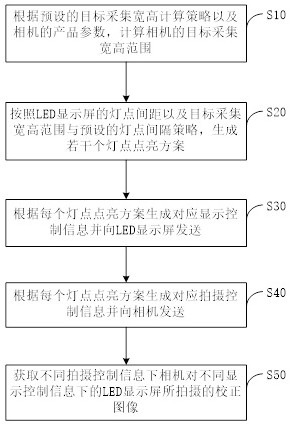
[0053] First of all, a kind of LED screen correction image acquisition method of the present invention, such as figure 1 shown, including the following steps:

[0054] S10: Calculate the target acquisition width and height range of the camera according to the preset target acquisition width and height calculation strategy and camera p...


PUM


Abstract

The invention relates to the technical field of LED display, and particularly discloses an LED screen correction image acquisition method, correction method, acquisition device and correction system. The acquisition method comprises the steps: calculating the target acquisition width and height range of a camera; generating a plurality of lamp point lightening schemes according to the lamp point spacing of the LED display screen, the target acquisition width and height range and a preset lamp point spacing strategy; generating corresponding display control information and shooting control information according to each lamp point lightening scheme; and obtaining correction images shot by the camera under the different shooting control information on the LED display screen under the different display control information, and the like. On the basis of meeting the data precision requirement, the correction images as few as possible are obtained, the image acquisition efficiency is improved, the CMOS pixels can be fully paved by the obtained correction images as much as possible, the problems of peripheral defocus, distortion and the like of the correction images in the prior art are solved, and the subsequent correction effect on the LED display screen is ensured.

Description

technical field [0001] The present invention relates to the technical field of LED screen calibration, in particular to a method for collecting calibration images of LED screens, a calibration method, a collection device and a calibration system. Background technique [0002] The equipment that must be used in the calibration process of the LED display is various types of cameras and various lenses that match the cameras. The host computer obtains the correction pictures through the cameras with the lenses, and calculates the correction coefficient through the correction pictures. [0003] However, since each lens has its own optimal magnification range, if the actual magnification of the lens is not within the optimal magnification range of the lens in actual use, the corrected image collected by the lens will appear out of focus As well as the problem of distortion, the data collected during the calibration process is inaccurate, which in turn affects the calibration effec...

Claims


Application Information

Patent Timeline
Patent Type & Authority Applications(China)
IPC IPC(8): G09G3/32
CPCG09G3/32
Inventor 何志民阮诗安
Owner SHENZHEN LIDING PHOTOELECTRIC TECH
Why Eureka
Try Eureka