
Peripheral field expansion device

a technology of expansion device and peripheral field, which is applied in the direction of instruments, spectacles/goggles, optics, etc., can solve the problems of interference with the normal central position of the person, and the location of image-shifting devices is not located in the central visual field

Active Publication Date: 2008-05-20
THE SCHEPENS EYE RES INST
View PDF12 Cites 22 Cited by
  • Summary
  • Abstract
  • Description
  • Claims
  • Application Information

AI Technical Summary

Benefits of technology

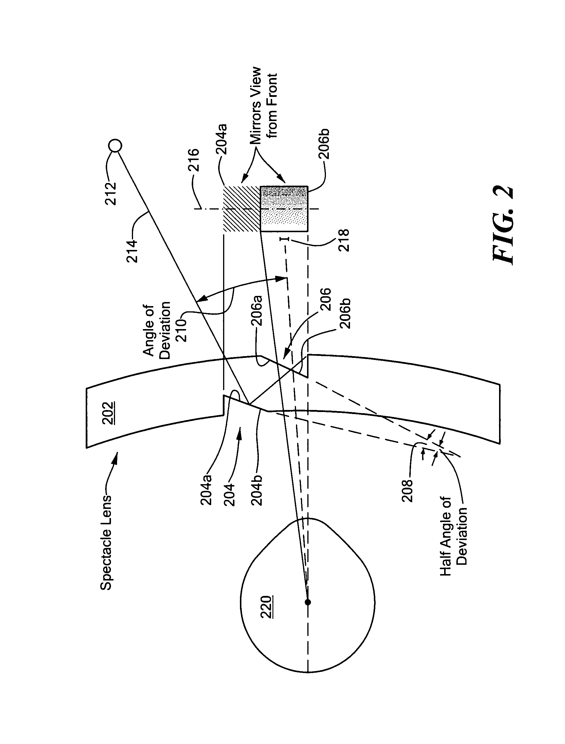
[0013]A spectacle system is disclosed for shifting the field expansion property of the peripheral prisms from the upper and lower peripheral visual fields toward the central visual field of a person with peripheral field loss and particularly hemianopia, while maintaining the lateral field expansion. In particular, in terms of the perceived image, the spectacle system includes image-shifting devices that shift the perceived images from the central missing visual fields toward the upper and lower peripheral visual fields. However, the image-shifting devices are not located in the central visual field where they may interfere with the person's normal central or foveal vision. The spectacle system can be fit onto, or formed within, one or both carrier lenses of a pair of spectacles and includes at least one image-shifting device. The image-shifting device is composed of a plurality of image-shifting elements. In one embodiment, the image-shifting device includes either a plurality of image-shifting prisms forming a Fresnel prism or a plurality of image-shifting mirror elements arranged to form a Fresnel-like mirrors based prism. The image-shifting elements are oriented such that the optical axis (base to apex axis in the case of a prism) of each image-shifting element forms an acute angle with the horizontal visual meridian of the person wearing the spectacles. In an alternative embodiment of a Fresnel-like mirrors based prism, the image-shifting mirror elements may be oriented such that the optical axis of each image-shifting element is parallel to the horizontal visual meridian of the person wearing the spectacles. The latter embodiment is similar in effect to the basic peripheral prisms described in the prior art but provides a more powerful prismatic effect than that possible with simple prisms.

Problems solved by technology

However, the image-shifting devices are not located in the central visual field where they may interfere with the person's normal central or foveal vision.

Method used


Image

  • Peripheral field expansion device
  • Peripheral field expansion device
  • Peripheral field expansion device

Examples


Embodiment Construction

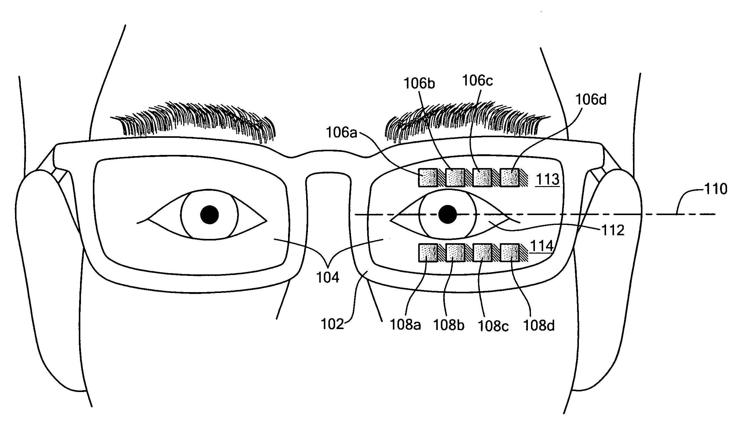
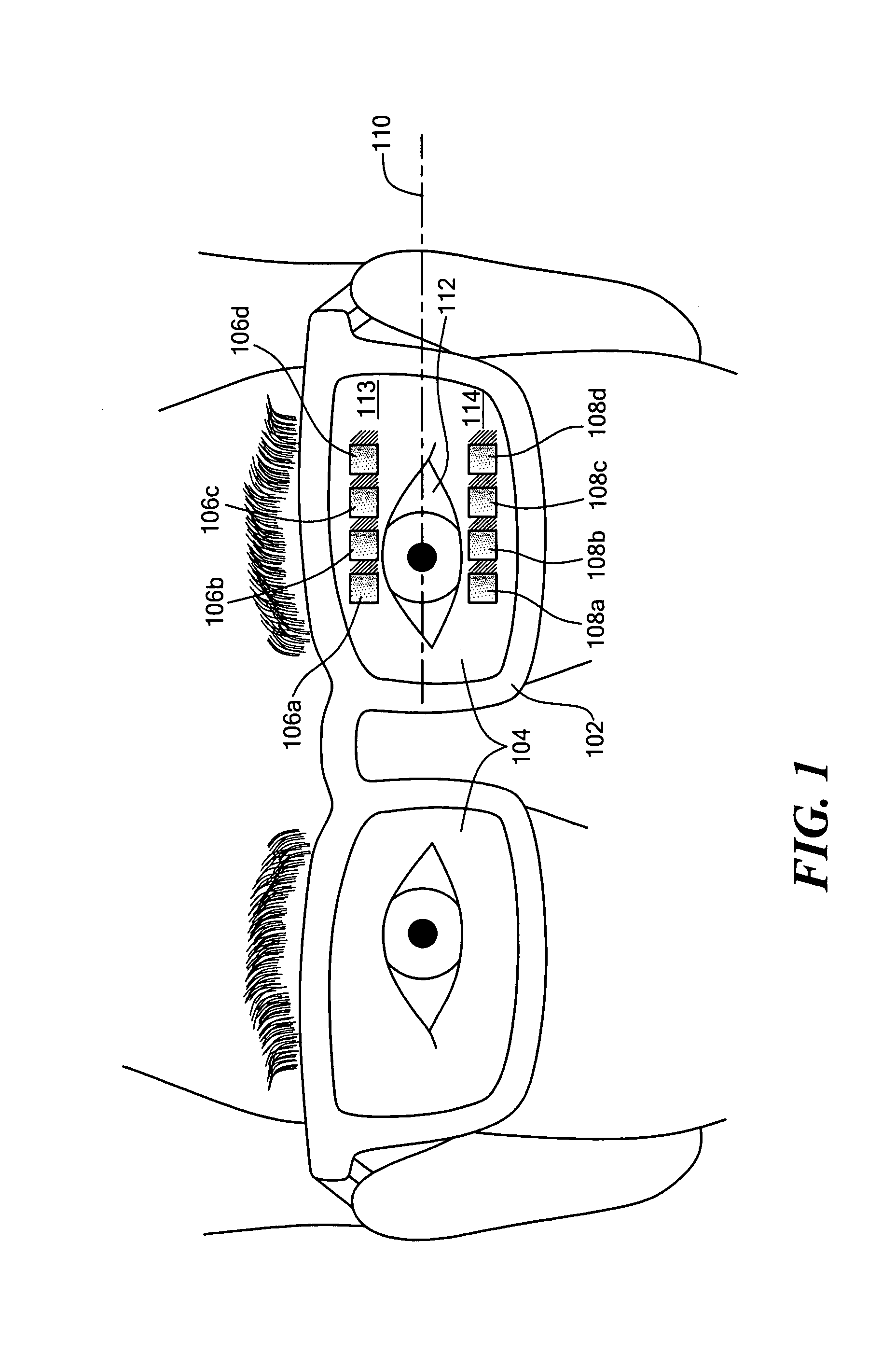
[0026]FIG. 1 depicts a front perspective view of one embodiment of the spectacle system of the present invention, the embodiment in which a plurality of image-shifting elements are configured and arranged to form a Fresnel-like mirror. In this embodiment, the image-shifting mirror elements are oriented such that the optical axis of each image-shifting element is parallel to the horizontal visual meridian of the person wearing the spectacles.

[0027]Referring to FIG. 1, a person in need of visual correction wears a spectacle frame 102 that includes carrier lenses 104. The viewing field through a carrier lens 104 is divided into a central viewing area 112, an upper peripheral viewing area 113 and a lower peripheral viewing area 114, where a horizontal meridian 110 aligned with the eyes of the wearer bisects the central viewing area and wherein the upper peripheral area is above the horizontal meridian and the lower peripheral area is below the horizontal meridian. The spectacle system o...


PUM


Abstract

A spectacle system is disclosed for shifting the field expansion property of peripheral prisms from the upper and lower peripheral visual fields toward the central visual field of a person with peripheral field loss, and particularly hemianopia, while maintaining the lateral field expansion. In terms of perceived image, the spectacle system includes image-shifting devices that shift the perceived images from the central missing visual fields toward the upper and lower peripheral visual fields. The image-shifting devices are placed out of the central visual field and do not interfere with the normal central or foveal vision of the wearer. The spectacle system can be fitted onto one or both carrier lenses of a pair of spectacles and includes at least one image-shifting device. The image-shifting device includes a plurality of image-shifting elements. In one embodiment, the image-shifting device includes a plurality of image-shifting mirror elements that are arranged to form a Fresnel-like mirrors based prism. In another embodiment, the image-shifting elements can include either a plurality of image shifting mirrors or a plurality of image-shifting prisms that are oriented such that the optical axis of each image-shifting element forms an acute angle with the horizontal visual meridian of the person wearing the spectacles.

Description

CROSS REFERENCE TO RELATED APPLICATIONS[0001]This application claims priority from U.S. Provisional Application No. 60 / 530,203, filed Dec. 17, 2003, entitled PERIPHERAL FIELD EXPANSION, the whole of which is hereby incorporated by reference herein.STATEMENT REGARDING FEDERALLY SPONSORED RESEARCH OR DEVELOPMENT[0002]Part of the work leading to this invention was carried out with United States Government support provided under a grant from the National Institutes of Health / National Eye Institute, Grant No. EY12890. Therefore, the U.S. Government has certain rights in this invention.BACKGROUND OF THE INVENTION[0003]Stroke, head injury and tumors commonly cause loss of peripheral vision in a condition called Hemianopia. The number of disabled stroke survivors in the United States is estimated to be more than 3 million annually. As many as one third of stroke survivors in rehabilitation have either Homonymous Hemianopia or Hemineglect.[0004]Homonymous Hemianopia, which is considered to b...

Claims


Application Information

Patent Timeline
Patent Type & Authority Patents(United States)
IPC IPC(8): G02C7/02G02C7/14G02B27/10G02C
CPCG02C7/14
Inventor PELI, ELIEZER
Owner THE SCHEPENS EYE RES INST
Learn More