Control of liquid crystal alignment in an optical device

a liquid crystal alignment and optical device technology, applied in the field of macroscopic liquid crystal alignment control, can solve the problems of not mentioning the spatially varying proportions of patterned alignment regions of kim et al, affecting the production viability of afm rubbing, and taking between 2 and 10 hours to rub an area

Active Publication Date: 2008-05-20
SHARP KK
View PDF14 Cites 94 Cited by
  • Summary
  • Abstract
  • Description
  • Claims
  • Application Information

AI Technical Summary

Benefits of technology

[0010]According to a first aspect of the present invention there is provided a method allowing simultaneous control of macroscopic azimuthal and zenithal liquid crystal (LC) alignment across a LC layer by controlling the area ratios between first, second and third different types of alignment region in a patterned alignment layer, the three different types of alignment region tending to induce LC alignment in the LC layer in three different respective, non-coplanar, principal orientations.
[0023]The variation mentioned above may be controlled such that the macroscopic pattern of liquid crystal alignment across the LC layer presents a varying retardation for incident light of a particular linear polarisation. The variation in retardation may provide a wavefront modulation function for light of that polarisation. The variation in retardation may provide a lens function for light of that polarisation.

Problems solved by technology

Kim et al do not disclose spatially varying the proportions of the patterned alignment regions or mention possible devices that could result from such patterning.
However, it takes between 2 and 10 hours to rub an area the size of a single pixel (90 μm×90 μm) using an atomic force microscope (AFM).
Consequently, AFM rubbing is not considered to be a production-viable technique
However, this zenithal patterning method relies on SiO and metal film deposition, and SiO deposition is not considered a production-compatible technique.
The fabrication method described by Ong et al could not be used to spatially vary the proportions of the homeotropic and planar alignment directions.
Ong et al do not disclose spatially varying the proportions of the patterned alignment regions or mention possible devices that could result from such patterning.
The techniques mentioned above are considered either to rely on commercially incompatible production methods or to have insufficient patterning flexibility to enable a number of novel optical elements to be made, or both.

Method used


Image

  • Control of liquid crystal alignment in an optical device
  • Control of liquid crystal alignment in an optical device
  • Control of liquid crystal alignment in an optical device

Examples


Embodiment Construction

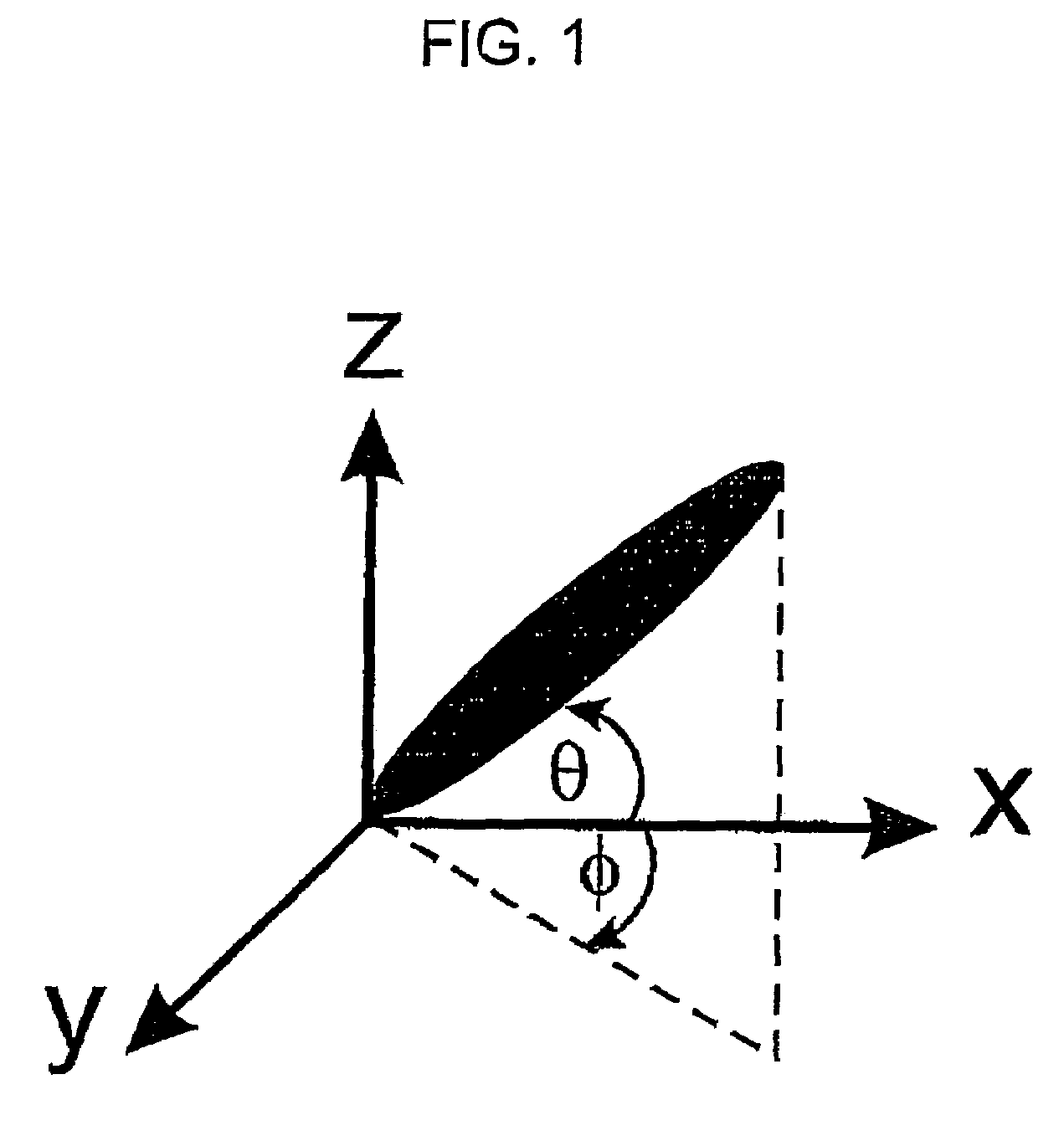
[0063]Before specific applications embodying the present invention are described, the general principles underlying embodiments of the present invention will first be described.

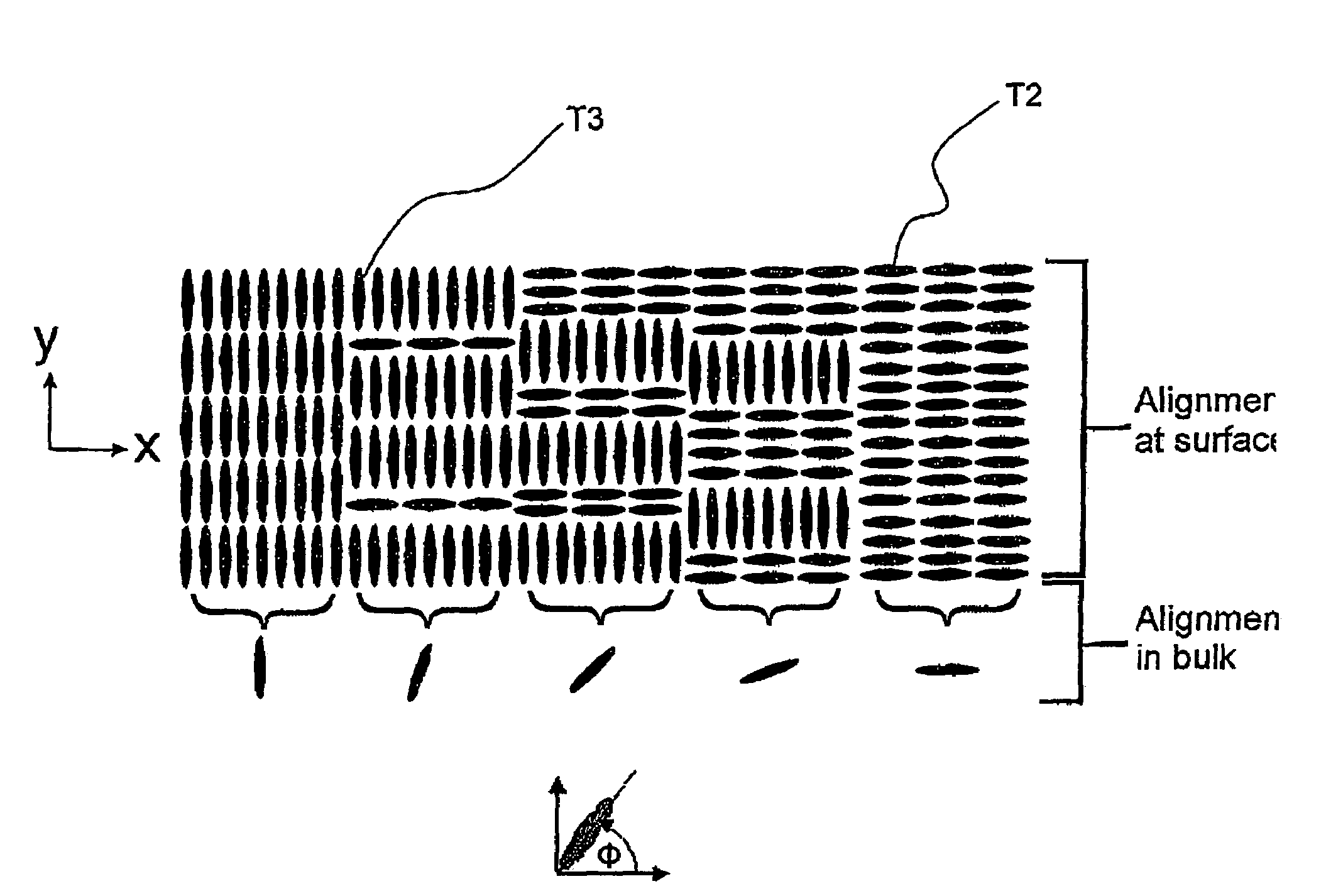
[0064]Consider a substrate that has an alignment layer that produces homeotropic alignment in its unprocessed state (i.e. LC molecular alignment is parallel with the z-axis in accordance with the coordinate system shown in FIG. 1 when the alignment layer has not been rubbed, or exposed to UV and so on). One patterned processing step can then be used to create regions of surface alignment parallel to one of the in-plane axes, say the x-axis. If a cell were to be constructed after one patterned processing step, then the bulk optic axis will lie in the x-z plane at all points within the cell (i.e. the molecular alignment has a constant value of φ at all points in the x-y plane). However, the angle that the optic axis makes with the substrate (θ) may or may not vary spatially in the x-y plane. Whether the optic a...


PUM

PropertyMeasurementUnit
widthaaaaaaaaaa
sizeaaaaaaaaaa
pre-tilt angleaaaaaaaaaa

Abstract

A method is provided that allows simultaneous control of macroscopic azimuthal and zenithal liquid crystal alignment (φ, θ) across a liquid crystal layer by controlling the area ratios between first, second and third different types of alignment region (T1, T2, T3) in a patterned alignment layer, the three different types of alignment region (T1, T2, T3) tending to induce liquid crystal alignment in the liquid crystal layer in three different respective, non-coplanar, principal orientations (z, x, y). In the illustrated example, the first type of alignment region (T1) tends to induce substantially homeotropic alignment (in the z direction) and the second and third types of alignment region (T2, T3) tend to induce substantially planar alignment in different, orthogonal, principal orientations (in the x and y directions). Control of macroscopic zenithal liquid crystal alignment (θ) is achieved by controlling the area ratios between the homeotropic (T1) and planar region types (T2, T3), and control of macroscopic azimuthal liquid crystal alignment (φ) is achieved by controlling the area ratio between the two planar region types (T2, T3).

Description

BACKGROUND OF THE INVENTION[0001]1. Field of the Invention[0002]The present invention relates to the control of macroscopic liquid crystal alignment in a liquid crystal layer, and to an optical device comprising a liquid crystal layer having its macroscopic liquid crystal alignment controlled in this way.[0003]2. Description of the Related Art[0004]FIG. 1 of the accompanying drawings illustrates the co-ordinate system of a LC director (average molecular orientation) in space. The angle θ is the zenithal (out of plane) angle while φ is the azimuthal (in-plane or planar) angle. The angle θ is also known as the tilt angle while φ is also known as the twist angle. The LC layer (or substrate) is in the x-y plane.[0005]Patterning of liquid crystal alignment on a gross scale is known. In this context, gross patterning refers to alignment regions that have a lateral extension larger than the thickness of the liquid crystal layer. The resulting liquid crystal layer has at least two domains t...

Claims


Application Information

Patent Timeline
Patent Type & Authority Patents(United States)
IPC IPC(8): G02F1/1337G02B5/30G02F1/13G02F1/137G02F1/139
CPCG02B5/3016G02F1/133753G02F1/1391G02F1/1395G02F2001/133738G02F2001/133757G02F2001/13787G02F2001/294G02F2001/133742G02F2001/133761G02F1/133738G02F1/133742G02F1/133761G02F1/133757G02F1/13787G02F1/294
Inventor SMITH, NATHANGASS, PAUL A.BRAMBLE, JONATHAN P.TILLIN, MARTIN D.MUSGRAVE, BRONJE M.
Owner SHARP KK
Why Eureka
Try Eureka