Device for modulating noise in a motor vehicle

a technology for motor vehicles and noise configurations, applied in the direction of engines, machines/engines, mechanical apparatus, etc., can solve the problem of requiring a relatively large outlay

Inactive Publication Date: 2008-05-27
DAIMLER AG
View PDF23 Cites 21 Cited by
  • Summary
  • Abstract
  • Description
  • Claims
  • Application Information

AI Technical Summary

Benefits of technology

[0008]As a result of this arrangement of the cross-flow openings between the chambers relative to the openings of the at least two gas conduits, the exhaust flow continues to flow through the two exhaust pipes and leaves the exhaust system, so that, with the device according to the invention, resonance discharge of the internal combustion engine is possible in a simple manner without adversely affecting the power and consumption of the engine.
[0009]With the extended path that the sonic waves must cover as a result of the connection according to the invention of the two gas conduits, and the acoustic coupling of the latter achieved therby, a phase shift between the two flows and the sonic waves associated with them in the respective gas conduits is achieved, as a result of which, in the case for example of a six-cylinder internal combustion engine, the canceling of the odd-numbered multiples of the 1.5th engine order is prevented. According to the invention, the odd-numbered multiples of the 1.5th engine order, that is to say the secondary orders, are thus once again part of the sound characteristic of the internal combustion engine, so that, in spite of the presence of the cross-flow section, a sporty sound characteristic of the engine can advantageously be achieved. A similar effect, that is to say a corresponding canceling of certain engine orders, is prevented in internal combustion engines with other numbers of cylinders.

Problems solved by technology

Precisely these secondary orders are however necessary for a sporty noise, so that internal combustion engines in a V-layout with exhaust systems of this type frequently have a sound which is regarded by the driver as not sporty enough.
This known device is effective, but it requires a relatively large outlay.

Method used


Image

  • Device for modulating noise in a motor vehicle
  • Device for modulating noise in a motor vehicle
  • Device for modulating noise in a motor vehicle

Examples


Embodiment Construction

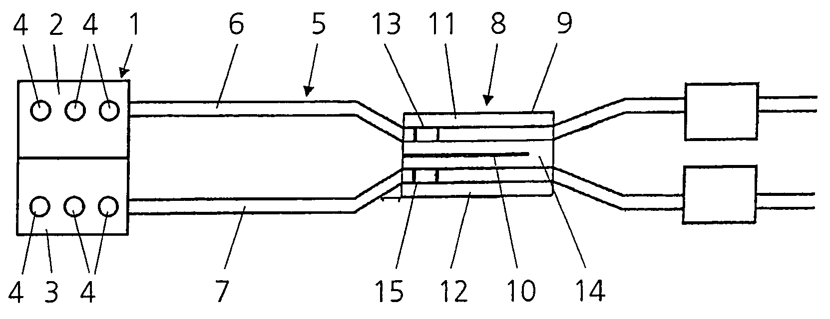
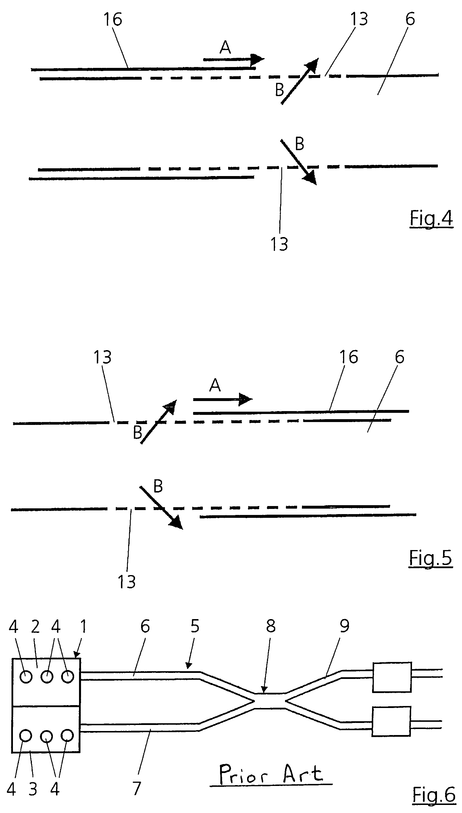
[0018]FIG. 6 shows a highly schematic illustration of an internal combustion engine 1 for a motor vehicle (not illustrated) which in the present case has two cylinder banks 2 and 3 which each have three cylinders 4. An intake system (not illustrated) which has corresponding inlet lines and which can be of known construction leads to the internal combustion engine 1 which is in a V-layout.

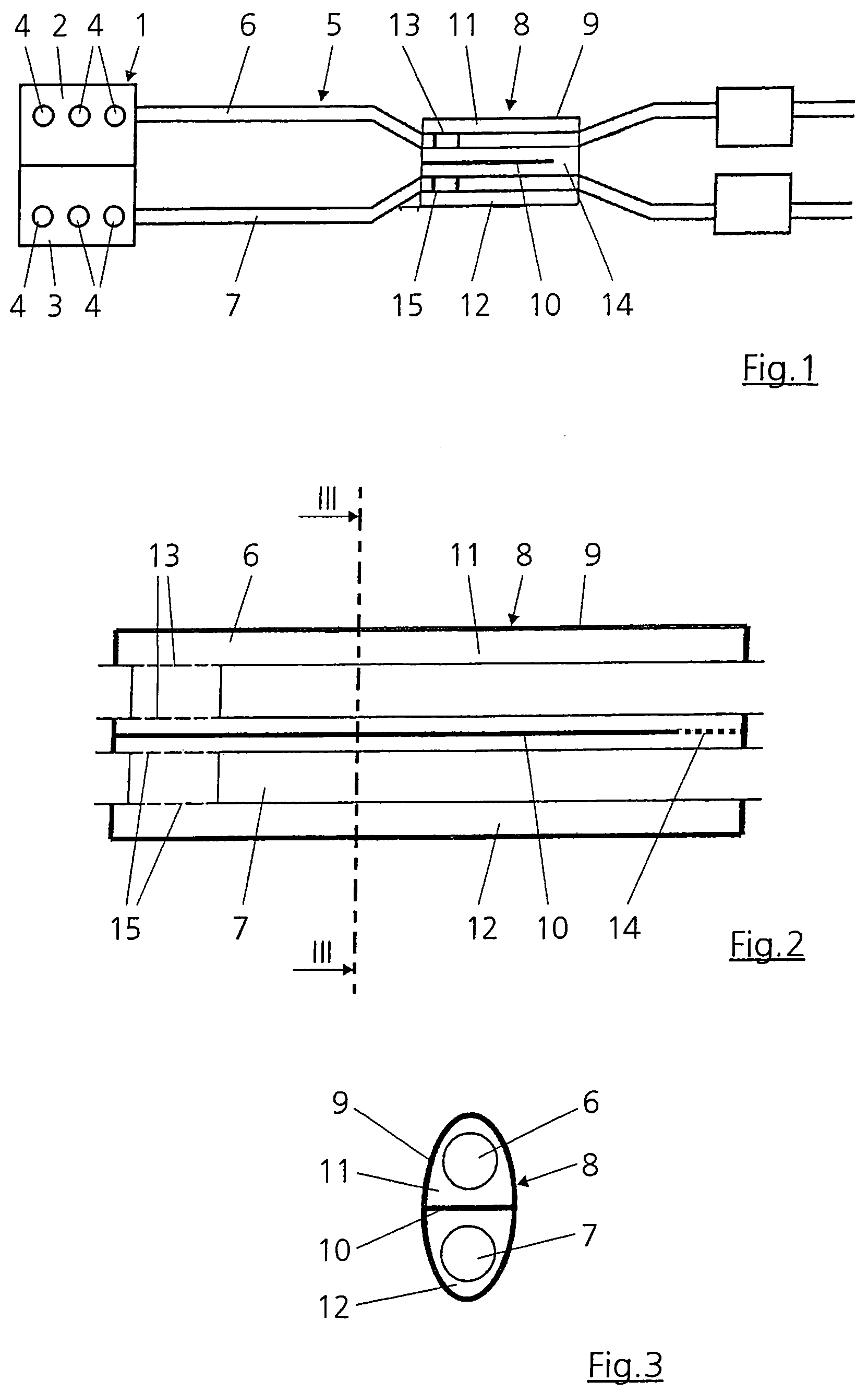
[0019]The exhaust gases which are produced in the cylinders 4 of the internal combustion engine 1 leave the latter by means of the exhaust system 5 which has two exhaust pipes 6 and 7, assigned to the two cylinder banks 2 and 3, respectively. The two exhaust pipes 6 and 7 are connected to one another by means of a so-called cross-flow section 8 which allows resonance discharge of the cylinders 4 of the internal combustion engine 1. Since the function principle of the cross-flow section 8 and the resonance discharge which this allows are known per se, these are not described in any further detail in ...


PUM


Abstract

In a device for noise configuration in a motor vehicle which has an internal combustion engine with at least two gas conduits connected to different cylinders of the engine, the gas conduits are interconnected by means of a cross-flow section formed by a housing which encloses the gas conduits and which has at least two chambers in each of which one of the gas conduits is disposed, each of the gas conduits being in communication with the respective chamber by which it is enclosed by means of a respective cross-flow opening and the two chambers being in communication with one another by means of at least one cross-flow opening which is remote from the cross-flow openings of the gas conduits so as to provide for a phase shift of the sound waves of the gas flowing through the housing.

Description

[0001]This is a continuation-in-part application of international application PCT / Ep2004 / 007498 filed Jul. 8, 2004 and claiming the priority of German application 103 31 620.5 filed Jul. 12, 2003.BACKGROUND OF THE INVENTION[0002]The invention relates to a device for noise configuration in a motor vehicle with an internal combustion engine having at least two exhaust conduits connected to different cylinders of the engine and having a cross-flow section each enclosed by a housing and the housings being in communication with each other by at least one cross-flow opening.[0003]In internal combustion engines having twin-pipe exhaust systems, it is known to provide a so-called cross-flow section between these two exhaust pipes in order to allow resonance discharge of the internal combustion engine. Such engines are normally internal combustion engines having six, eight or twelve cylinders in a V arrangement.[0004]As a result of the ignition sequence of internal combustion engines of this...

Claims


Application Information

Patent Timeline
Patent Type & Authority Patents(United States)
IPC IPC(8): F01N7/04F01N1/06F01N1/16F01N13/04
CPCF01N1/06F01N13/017F01N13/04F01N1/165
Inventor HOFMANN, MARCUSROSSA, SASCHASTAROBINSKI, ROUDOLF
Owner DAIMLER AG
Why Eureka
Try Eureka