Electrical panel box

Inactive Publication Date: 2008-06-03
FRUSCO LOUIS J
View PDF10 Cites 15 Cited by
  • Summary
  • Abstract
  • Description
  • Claims
  • Application Information

AI Technical Summary

Benefits of technology

[0010]A still further object of the present invention is to provide for a novel electrical panel box having an additional access panel which allows access to the top portion or bottom portion of the electrical panel box for the snaking of additional electrical conduit, cable or wires which provides safety to the electrician and prevents the possibility of shorts and flashes.
[0011]A still further obj

Problems solved by technology

The problem which the electrician faces is when a homeowner adds new electrical requirements to an existing residence.
Since the electrician is attempting to snake the conduit, cable or wire with a metal snake thr

Method used


Image

  • Electrical panel box
  • Electrical panel box
  • Electrical panel box

Examples


Embodiment Construction

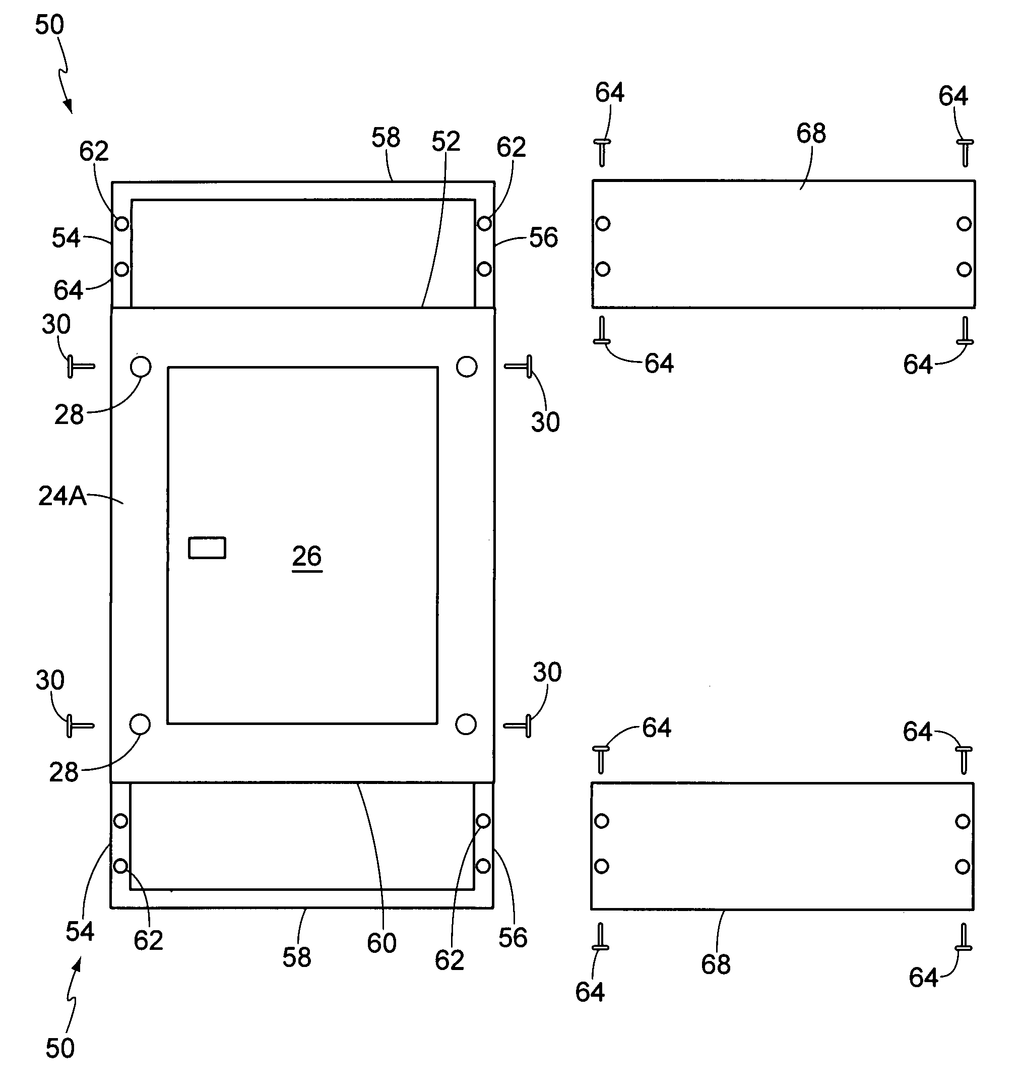
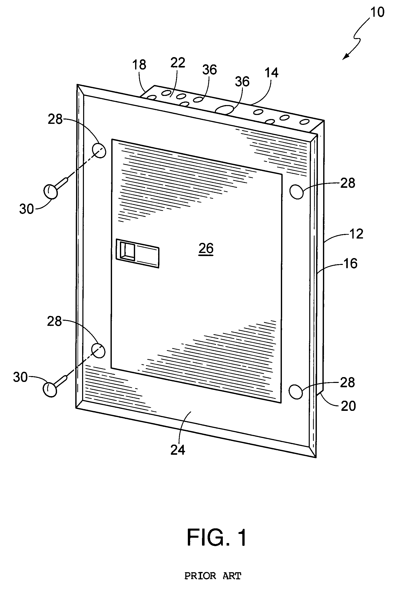
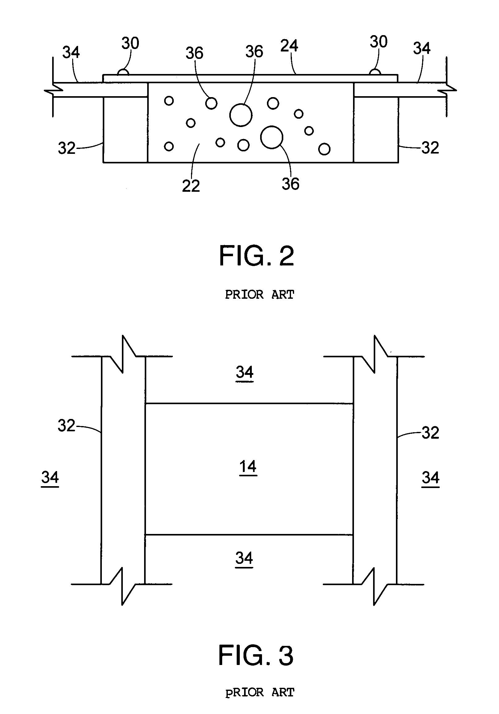
[0020]FIG. 1 is a perspective view of a typical electrical panel box 10 of the prior art. Electrical panel box 10 is comprised of a housing portion 12 defined by a back wall 14, opposing side walls 16 and 18, a bottom wall 20 and a top wall 22. A front wall 24 is secured to the housing member 12, front wall 24 having a hinged door 26 allowing access to the interior of the housing where after fully wired, the various circuit breakers would be located. Front wall 24 extends beyond the periphery of housing member 12 and is formed with a plurality of apertures 28 for the receipt of threaded fasteners 30. The housing member 12 is dimensioned from side wall 16 to side wall 18 to fit snugly between adjacent vertical wall studs 32 and be secured thereto (See FIGS. 2 and 3). The extended periphery of front face 24 is dimensioned such that threaded fasteners 30 passing through the apertures 28 will engage into the adjacent wall 34 thereby securing the electrical panel box.

[0021]FIG. 1 also il...


PUM


Abstract

An electrical panel box which includes a cavity defined by a back face, two opposing side walls, a top wall and a bottom wall and a front face extending beyond the periphery of the side walls and top and bottom walls for securing the electrical panel box in a wall, the front face being fitted with mounting brackets on either its top edge or its bottom edge or both, the mounting bracket having secured thereto an access plate which allows the electrician access to the region directly above the top wall of the housing or the below the bottom wall of the housing so as to permit snaking of additional electrical conduit, cable or wires without having concern for contacting the main electrical conduit into the house thus causing a short or a flash and possible injury to the electrician.

Description

BACKGROUND OF THE INVENTION[0001]1. Field of the Invention[0002]The present invention is related to electrical circuitry, and in particular, the electrical panel box from which electrical cables distribute power to various locations within a residence, commercial building or industrial complex.[0003]2. Description of the Prior Art[0004]All residential, commercial locations, and industrial locations have at least one electrical panel box located within the structure which serves as the load center to distribute via electrical conduit, cable, or wires power to various locations within the structure. These electrical panel boxes or load centers are commonly referred to in a residential setting as the breaker panel box as it allows the home owner to disrupt electrical power to various portions of the residence. The box also serves as a safety feature in that a surge or overload will cause the breakers to engage so as to prevent damage from such surge or overload. The panels of the prior...

Claims


Application Information

Patent Timeline
IPC IPC(8): H02G3/08
CPCH02G3/10
Inventor FRUSCO, LOUIS J.
Owner FRUSCO LOUIS J
Why Eureka
Try Eureka