Multistage lock cylinder assembly

a multi-stage, lock technology, applied in the direction of puzzle locks, building locks, construction, etc., can solve the problem of taking few time for an unauthorized person, and achieve the effect of improving the safety of using increasing the difficulty of unlocking the lock cylinder assembly

Inactive Publication Date: 2008-06-10
LIU WEN KUEI +2
View PDF13 Cites 7 Cited by
  • Summary
  • Abstract
  • Description
  • Claims
  • Application Information

AI Technical Summary

Benefits of technology

[0008]The main objective of the invention is to provide a lock cylinder assembly that can increase the difficulty of unlocking the lock cylinder assembly to improve the safety of using the lock cylinder assembly.

Problems solved by technology

However, the conventional lock cylinder assembly has only one disk set (60) including three disks (61,62,63), to unlock the lock cylinder assembly only needs three passwords, is easy and takes few time for an unauthorized person.

Method used


Image

  • Multistage lock cylinder assembly
  • Multistage lock cylinder assembly
  • Multistage lock cylinder assembly

Examples


Embodiment Construction

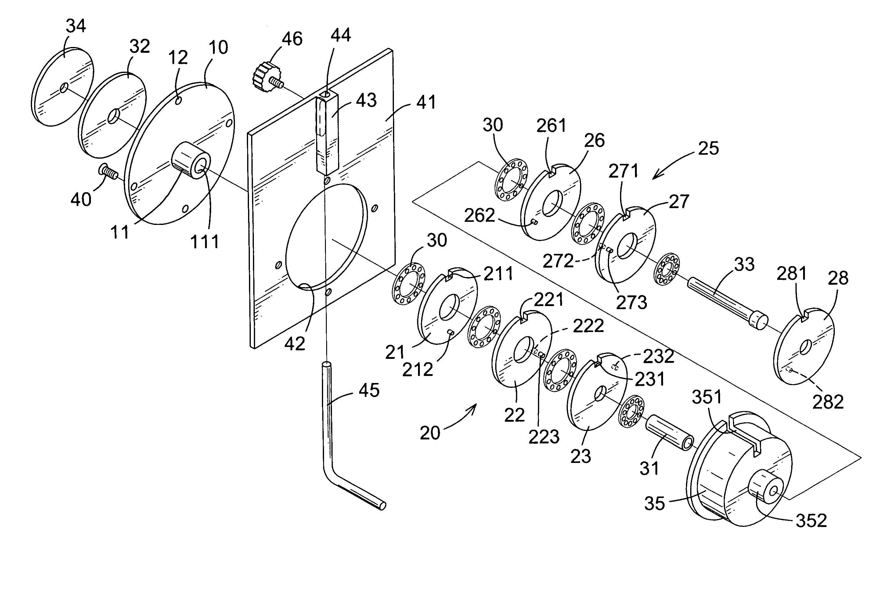
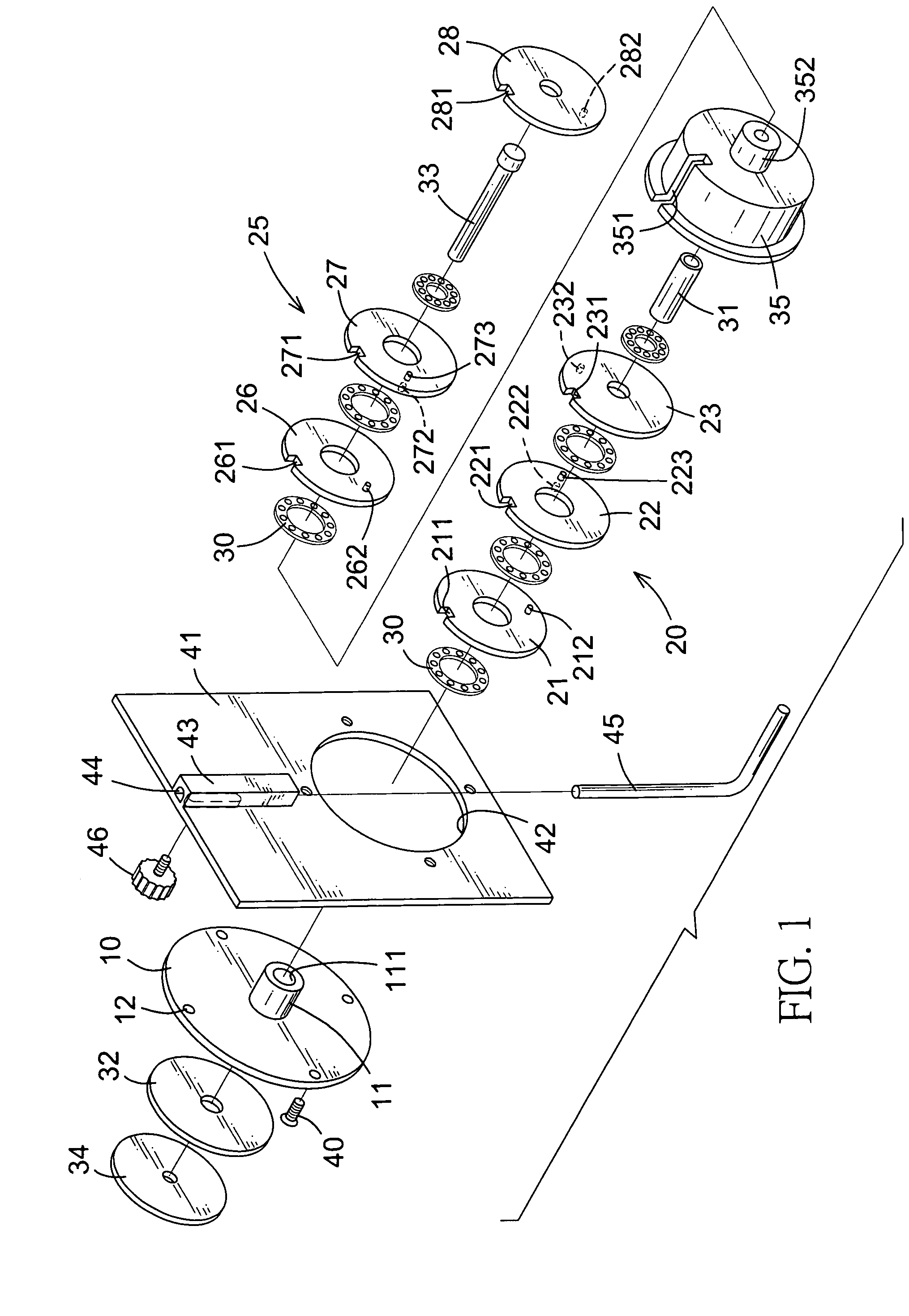
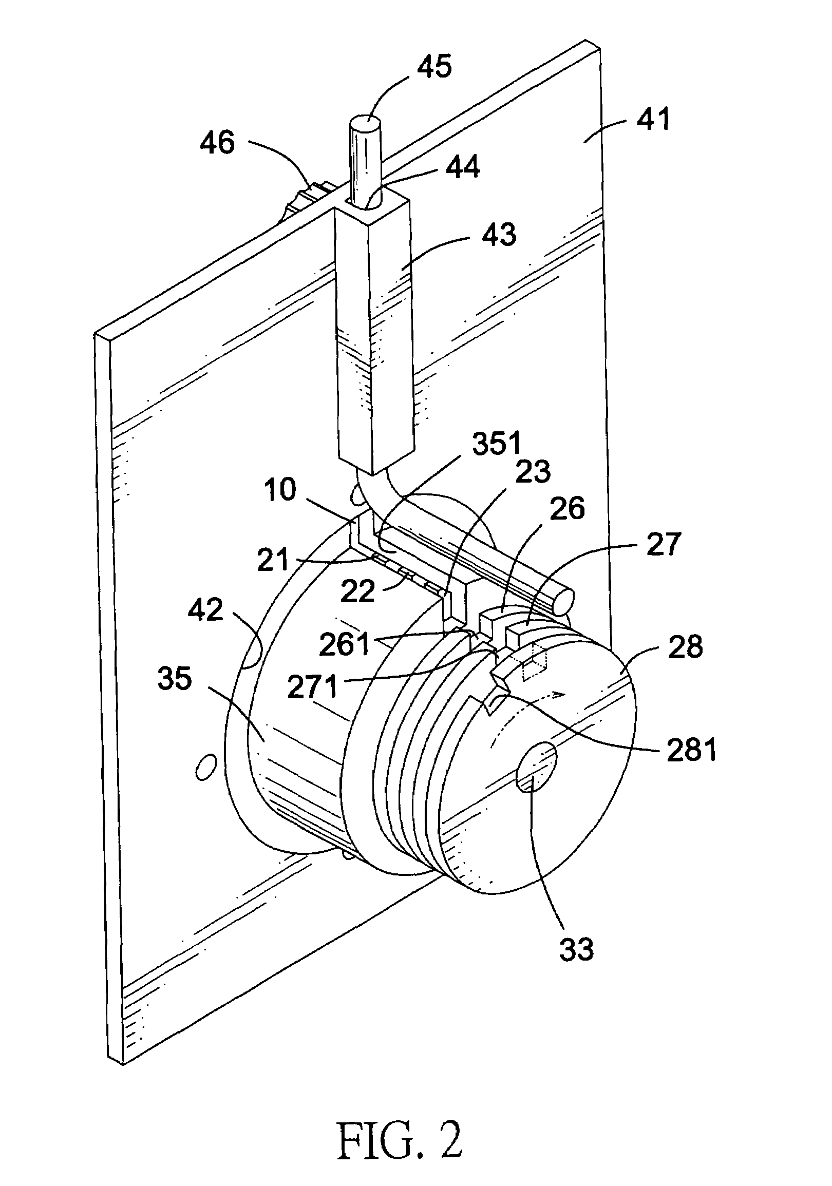
[0021]With reference to FIGS. 1 to 5, a lock cylinder assembly in accordance with the present invention is applied for a lock device and comprises a base (10), multiple selecting disks (32,34) and multiple disk sets (20,25). The lock device has a board (41), an L-shaped lock bolt (45) and a knob (46). The board (41) has a bolt holder (43) formed on one side of the board (41). The bolt holder (43) has a channel (44) defined through the bolt holder (43). The L-shaped lock bolt (45) has a first end slidably inserted into the channel (44) in the bolt holder (43) and a second end corresponding to the lock cylinder assembly. The knob (46) movably extends into the bolt holder (43) and is securely connected to the first end of the lock bolt (45) to move the lock bolt (45) along the channel (44) in the bolt holder (43).

[0022]The base (10) has an axis and a central tube (11) extending from the base (10) along the axis and multiple through holes (12) defined through the base (10) and around th...


PUM


Abstract

A lock cylinder assembly has a base, multiple selecting disks and multiple disk sets. The base has an axis. The selecting disks are rotatably connected to the base along the axis of the base. The disk sets are operationally mounted along the axis of the base and are respectively connected to the selecting disks. Each disk set has multiple disks operationally mounted along the axis of the base. Accordingly, a lock cylinder assembly that can increase the difficulty of unlocking the lock cylinder assembly to improve the safety of using the lock cylinder assembly is provided.

Description

BACKGROUND OF THE INVENTION[0001]1. Field of the Invention[0002]The present invention relates to a lock cylinder assembly, and more particularly to a multistage lock cylinder assembly to improve the safety provided by the lock cylinder assembly.[0003]2. Description of Related Art[0004]With reference to FIGS. 9 and 10, a conventional lock cylinder assembly applied for a lock device in accordance with the prior art comprises a base (50), a knob (54) and a disk set (60). The base has a central tube (51), multiple through holes (52) and an indicator (55). The central tube (51) is formed on and extends from the base (50). The through holes (52) are defined through the base (50) and around the central tube (51). With multiple fasteners extending through the through holes (52), the base (50) is secured to an object on which the lock cylinder assembly is mounted. The knob (54) is rotatably mounted on the base (50) and has a driving rod (53) extending through the base (50) and the central tu...

Claims


Application Information

Patent Timeline
Patent Type & Authority Patents(United States)
IPC IPC(8): E05B37/02
CPCE05B37/00E05B37/0096E05B37/08Y10T70/7237Y10T70/7266Y10T70/7243Y10T70/7294
Inventor LIU, WEN-KUEILIU, CHAO-HSUANLIU, YU-CHUN
Owner LIU WEN KUEI
Why Eureka
Try Eureka