Disassembly-prevention exhaust lock valve

An exhaust valve, anti-disassembly technology, applied in valve details, valve devices, devices to prevent accidental or unauthorized action, etc. problems, to achieve the effect of extending the service life, preventing the loss of hot water, and having a wide range of applications

Inactive Publication Date: 2017-07-14
周贯章
View PDF4 Cites 2 Cited by
  • Summary
  • Abstract
  • Description
  • Claims
  • Application Information

AI Technical Summary

Problems solved by technology

[0003] CN202852167U discloses a combined exhaust lock valve, which includes a composite lock and a needle exhaust valve, the dead bolt of the composite lock snaps into the lock groove of the exhaust valve to form a combined structure, and the composite lock is opened with a key when exhausting Make it out of the needle exhaust valve, and then adjust the needle exhaust valve to achieve deflation. This lock valve solves the problem of users opening the valve to release water to a certain extent, but the composite lock is difficult for professional lock unlockers to open. It is not difficult, so it is still impossible to completely eliminate the phenomenon of water theft. In addition, when the composite lock and the needle exhaust valve are assembled, they are axially connected, and the lock tongue and spring arranged at the joint take up a lot of space. restricted

Method used


Image

  • Disassembly-prevention exhaust lock valve
  • Disassembly-prevention exhaust lock valve
  • Disassembly-prevention exhaust lock valve

Examples


Embodiment Construction

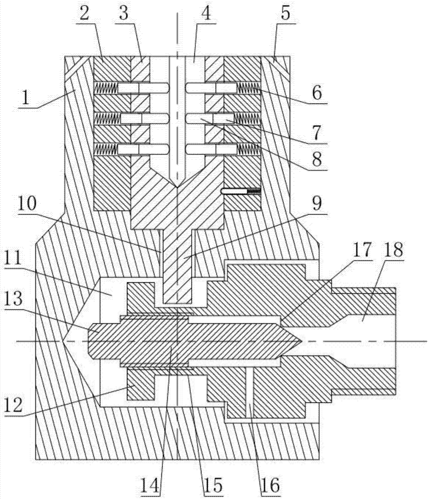
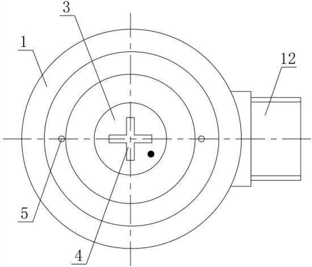
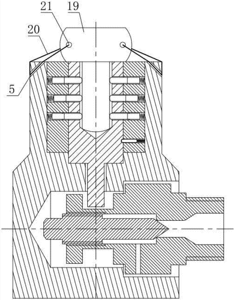
[0021] Such as Figure 1-Figure 6 As shown, the anti-disassembly exhaust lock valve includes a needle exhaust valve and a composite lock. The composite lock is composed of a tamper-proof cover 1, an anti-theft lock built in the upper part of the tamper-proof cover 1, a key (omitted in the figure) and a sealing piece 19 that cooperate with the anti-theft lock. The lateral opening of the exhaust valve is inserted into the cavity 11 horizontally. The top of the laterally inserted cavity 11 is provided with a longitudinal through hole 10 communicating with the upper part of the anti-demolition cover 1. The bottom surface of the lock cylinder 3 of the anti-theft lock is provided with a The lock pin 9 moved by the longitudinal through hole 10, the outer peripheral surface of the lock core 3 is provided with an oblique arc U-shaped groove 22, and the inner peripheral surface of the lock body 2 of the anti-theft lock is provided with an oblique arc U-shaped groove. 22 corresponding t...


PUM


Abstract

The invention relates to a disassembly-prevention exhaust lock valve comprising a needle type exhaust valve and a composite lock. The disassembly-prevention exhaust lock valve is characterized in that the composite lock is composed of a disassembly-prevention cover, an anti-theft lock arranged in the upper portion of the disassembly-prevention cover, a key matched with the anti-theft lock, and a seal sheet; a transverse insertion cavity corresponding to a lateral opening of the needle type exhaust valve is formed in the lower portion of the disassembly-prevention cover; a longitudinal through hole communicating with the upper portion of the disassembly-prevention cover is formed in the top of the transverse insertion cavity; a lock pin moving along the longitudinal through hole is arranged on the bottom face of a lock cylinder of the anti-theft lock; an inclined arc U-shaped groove is formed in the peripheral face of the lock cylinder; a positioning pin and a positioning spring which correspond to the inclined arc U-shaped groove are arranged on the inner circumferential face of a lock body of the anti-theft lock; an annular lock groove is formed in the front end of a valve body of the needle type exhaust valve; and after the needle type exhaust valve is inserted in the transverse cavity, the tail end of the lock pin is clamped in the annular lock groove of the needle type exhaust valve. By means of the disassembly-prevention exhaust lock valve, hot water in a pipe network is prevented from being lost; and compared with an existing combined exhaust lock valve, the unlocking difficulty is increased, the size is reduced, and the application range is wide.

Description

technical field [0001] The invention relates to an exhaust lock valve structure in a heating pipe network, in particular to an anti-disassembly exhaust lock valve, which is suitable for a special person to be responsible for removing the gas that affects the flow of heating hot water in the pipe network, preventing others from unlocking, preventing water theft, and eliminating heat loss. Background technique [0002] At present, the exhaust valve structure commonly used in the heating pipe network is a needle exhaust valve, also called an exhaust valve and a run-off valve. This is an exhaust valve that the user can adjust the exhaust action by himself. , the hot water in the heating pipe network is easily released, causing a large amount of hot water loss, wasting a lot of water and electricity resources, causing large economic losses to the heating unit, and seriously affecting the heating effect. To replenish the missing water in the pipeline network, cold water needs to ...

Claims


Application Information

Patent Timeline
Patent Type & Authority Applications(China)
IPC IPC(8): F16K35/10
CPCF16K35/10
Inventor 周贯章
Owner 周贯章
Why Eureka
Try Eureka