Cleaning sheet

a technology of cleaning sheets and adhesives, applied in the field of disposable cleaning sheets, can solve the problems of entanglement and difficulty in removing large solid particles, debris may be trapped by sticky parts, and dust and debris may be difficult to remov

Inactive Publication Date: 2008-06-17
KAO CORP
View PDF17 Cites 58 Cited by
  • Summary
  • Abstract
  • Description
  • Claims
  • Application Information

AI Technical Summary

Problems solved by technology

The conventionally employed cleaning sheets are capable of entrapping hair, lint, soil or like dust and debris by entanglement in the fibers of nonwoven fabric but have difficulties in holding by entanglement all the dust and debris, from fine dust to solid particles of about 1 mm or greater in size, such as sand, pebbles, food crumbs, rice grains, and sesame seeds.
Such large solid particles cannot be removed but with a dustpan or a vacuum cleaner.
Therefore, a user must aim at the debris and press the cleaning sheet onto the debris with a certain force so that the debris may be trapped by the sticky parts.
Even when a user presses a cleaning tool to catch debris, however, the dust trapping efficiency is low because the tacky parts are disposed in parts.
Moreover, if large ones of various kinds of dust that have not been entangled in the fibers, i.e., large diameter dust particles or thick dust particles, are the first to be trapped by the tacky parts, the wiping part of the cleaning sheet is hindered by the large dust particles from coming into intimate contact with the surface to be cleaned.
As a result, the cleaning sheet is incapable of catching dust sufficiently.
Merely having the recesses, the cleaning sheet has low capability of catching and holding the above-mentioned relatively large solid dust and is therefore incapable of trapping such dust sufficiently.
While the wiping material can keep the side portions a little distance away from the floor, etc., dust particles having a different size (height) from that distance are not brought into contact with the side portions, and the wiping material shows no collecting and trapping performance for the dust particles.
When the wiping material is used in a usual sweeping operation (for example, sliding the wiping portion on a floor, etc.), it has difficulty in catching relatively large solid dust particles of the above stated size.

Method used


Image

  • Cleaning sheet
  • Cleaning sheet
  • Cleaning sheet

Examples


first embodiment

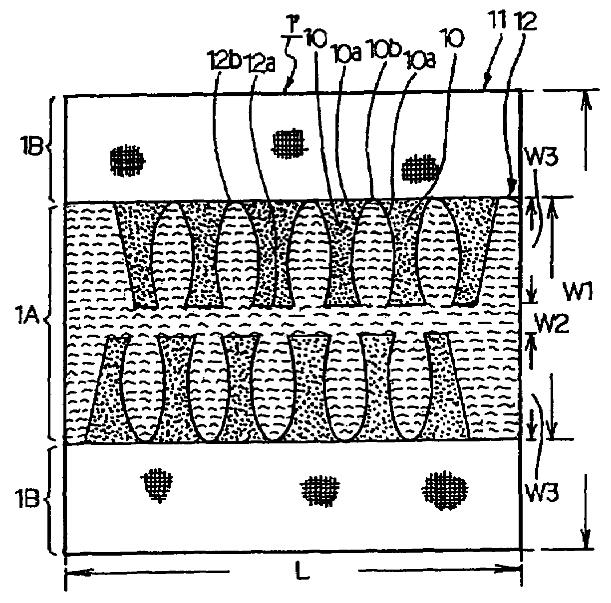
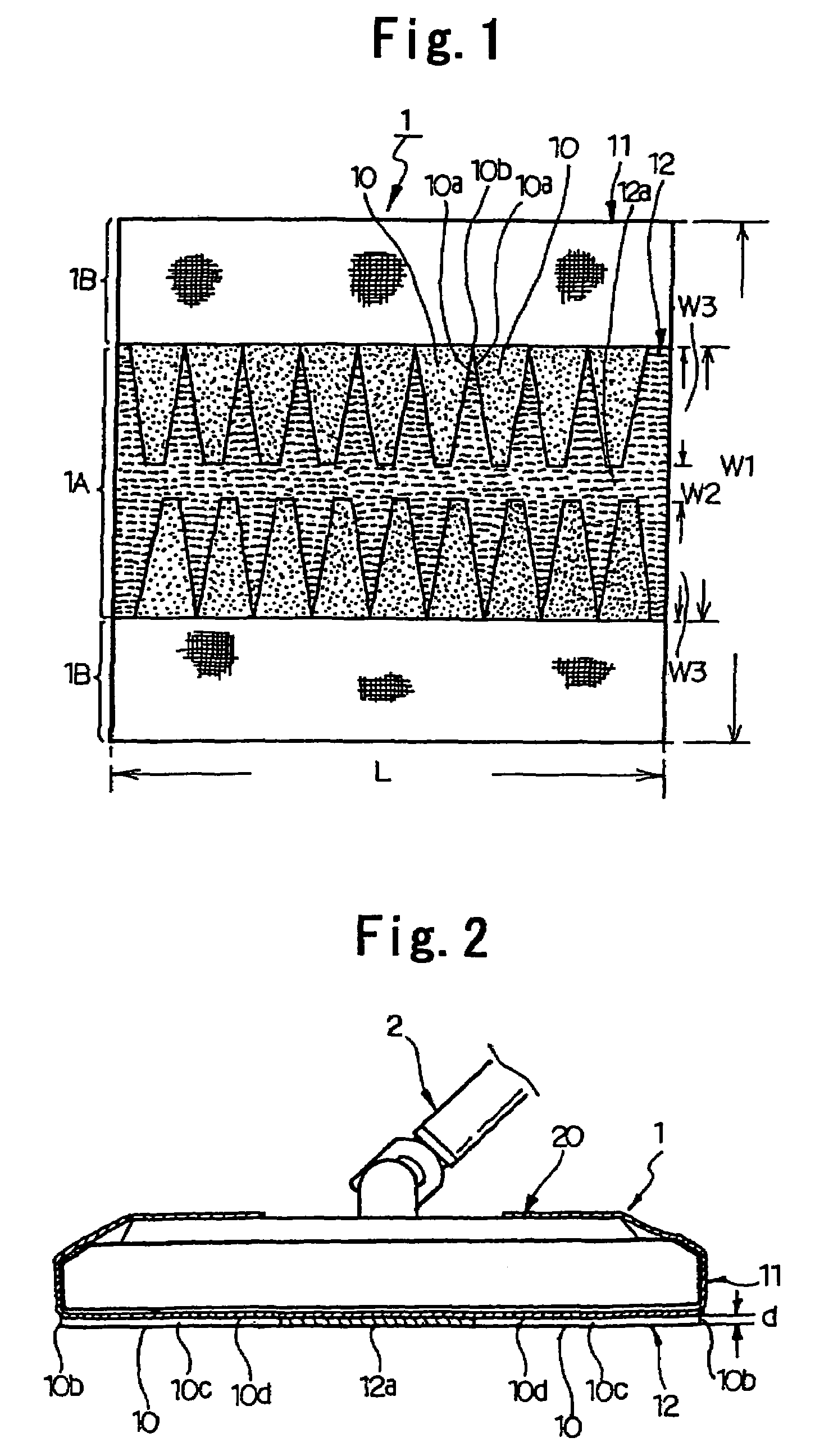
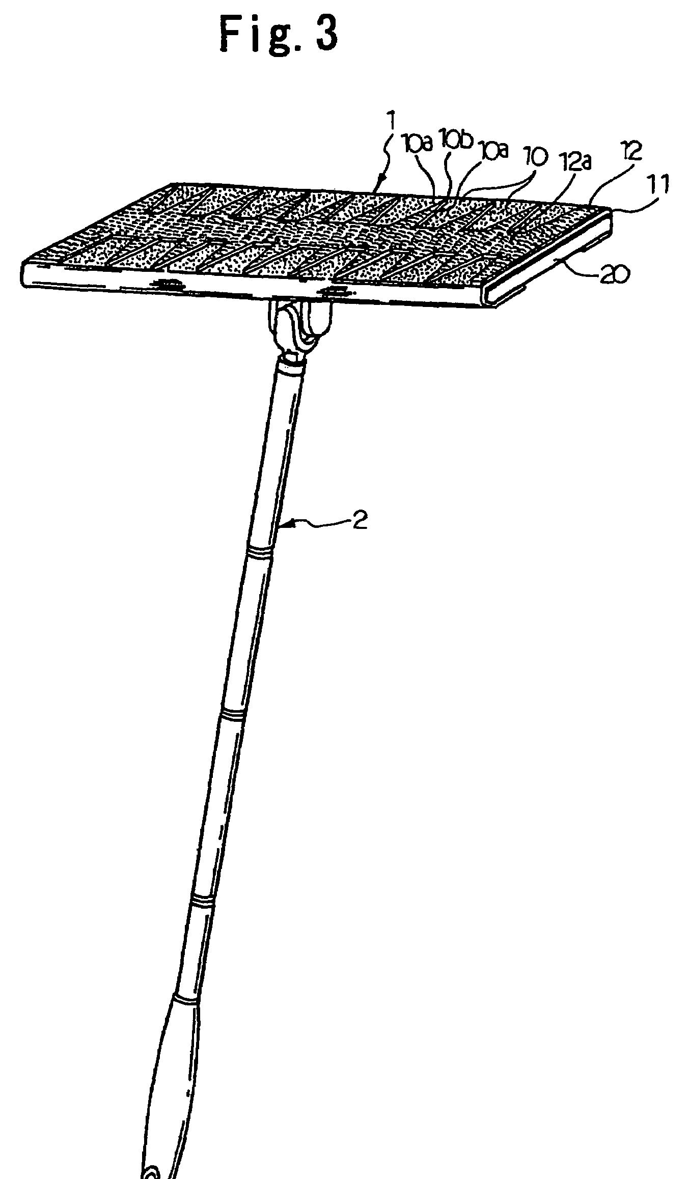
[0041]FIGS. 1 to 3 illustrate the cleaning sheet according to the present invention. FIGS. 2 and 3 show the state of the cleaning sheet being attached to the head of a cleaning tool. In these figures, numerals 1 and 2 indicate the cleaning sheet and the cleaning tool, respectively.

[0042]As shown in FIG. 1, the cleaning sheet 1 has a rectangular shape in its plan view. The cleaning sheet 1 has a wiping portion 1A and fixing portions 1B located on both sides of the wiping portion 1A. In the state attached to the head 20 of the cleaning tool 2 as illustrated in FIGS. 2 and 3, the wiping portion 1A is disposed on the lower side of the head 20, and the fixing portions 1B are fixed to the upper side of the head 20.

[0043]While the cleaning sheet 1 is not particularly limited in size and shape, it is preferred that both length L and width W2 fall within ±30% of the length and the width, respectively, of the lower side of the head 20 of the cleaning tool 2. As the area of the head 20 of the ...

second embodiment

[0060]The cleaning sheet of the present invention can have the area of the recesses 10 increased by increasing the length W3 of the recesses 10 in the width direction of the wiping portion so as to have increased dust collecting capacity as in the cleaning sheet 1′ of the second embodiment shown in FIG. 4.

[0061]The wiping sheet 12 may have isosceles-triangular cutouts from its front and the rear edges in its plan, resulting in formation of isosceles-triangular recesses 10 in the plan view as in the cleaning sheet 1′ of the third embodiment shown in FIG. 5. The cleaning sheet 1′ of the third embodiment offers the following effect as well as the effects of the cleaning sheet 1 of the first embodiment. Because the recesses 10 taper toward the middle of the wiping portion 1A, dust is squeezed into the narrow depth of the recesses 10 near the middle of the wiping portion 1A.

[0062]The cleaning sheet 1′ of the third embodiment may have the area of the individual recesses 10 increased by na...

sixth embodiment

[0064]As in the cleaning sheet 1′ of the sixth embodiment shown in FIG. 8, the wiping sheet 12 may have no strip part 12a, and the recesses 10 of the front row may be interconnected to the recesses 10 of the rear row in such a configuration that the interconnected recesses 10 are impenetrable from the front or the rear. According to this design, the recesses 10 can have increased area, and relatively large dust particles can be collected even in the widthwise middle of the wiping portion 1A. Since the recesses 10 are impenetrable from the front or the rear, the dust once collected in the recess is not allowed to get through.

[0065]As in the cleaning sheet 1′ of the seventh embodiment illustrated in FIG. 9, the wiping part 1A may be designed such that there is no strip part 12a and that diamond-shaped (parallelogramic) pieces of the wiping sheet 12 are fixed on the base sheet 11 in a diamond lattice pattern instead of the comb tooth-like arrangement of the first embodiment. This arran...


PUM

PropertyMeasurementUnit
sizeaaaaaaaaaa
width W2aaaaaaaaaa
width W2aaaaaaaaaa

Abstract

A cleaning sheet adapted to be attached to the head (20) of a cleaning tool (2) and having a wiping portion (1A) adapted to be disposed on the lower side of the head (20). In the state attached to the head (20), the cleaning sheet has, in the wiping portion (1A) thereof, a plurality of tacky recesses (10) open to the front and the rear of the head (20). The cleaning sheet has pointed parts (10b) projecting to the front and the rear between borders (10a) of adjacent two of the recesses (10).

Description

TECHNICAL FIELD[0001]The present invention relates to a disposable cleaning sheet that is primarily adapted to be attached to the head of a cleaning tool and to be used to collect and trap dust and debris, such as house dust.BACKGROUND ART[0002]A variety of cleaning implements have been proposed for cleaning the surface of furniture, walls, and floors of houses, automotive interior trim, and the like. Amongst them is a cleaning tool having a handle and a head to which a cleaning sheet made of nonwoven fabric, etc. is attached.[0003]The conventionally employed cleaning sheets are capable of entrapping hair, lint, soil or like dust and debris by entanglement in the fibers of nonwoven fabric but have difficulties in holding by entanglement all the dust and debris, from fine dust to solid particles of about 1 mm or greater in size, such as sand, pebbles, food crumbs, rice grains, and sesame seeds. Such large solid particles cannot be removed but with a dustpan or a vacuum cleaner.[0004]...

Claims


Application Information

Patent Timeline
Patent Type & Authority Patents(United States)
IPC IPC(8): A47L25/00A47L13/16A47L13/20
CPCA47L13/20A47L13/16
Inventor OTSUKA, HIROSHIYANAGIDA, HIROYUKI
Owner KAO CORP
Why Eureka
Try Eureka