Radio frequency isolation container

a technology of isolation container and radio frequency, which is applied in the direction of gaseous cathodes, electric apparatus casings/cabinets/drawers, instruments, etc., can solve the problems of the locking mechanism of the conventional rf isolation container can also be problematic, and the type of motion/pressure that needs to be applied

Active Publication Date: 2008-06-17
MALIKIE INNOVATIONS LTD
View PDF5 Cites 17 Cited by
  • Summary
  • Abstract
  • Description
  • Claims
  • Application Information

AI Technical Summary

Problems solved by technology

Conventional RF isolation containers present several problems, particularly in a manufacturing environment.
In the area of ergonomics, there may be issues with the types of motions / pressures that need to be applied in the operation of the RF isolation container.
For example, the locking mechanism in conventional RF isolation containers can also be problematic from a health and safety viewpoint.
This additional pressure requirement and the additional movements and possible jarring required can lead to health and safety issues, such as repetitive strain injury and the like.
In the area of maintenance, there can be issues related to the number / type of parts in an RF isolation container.
For example, from a maintenance standpoint, it can be difficult to determine when gas cylinders used in supporting the lid may need maintenance or be likely to break.
As such, there are difficulties in ensuring that the gas cylinder supports for the container lid are functioning correctly.
If the gas cylinders fail while a worker has a hand inside the RF isolation container, there is a safety issue.
Another maintenance issue relates to cleaning of the conventional RF isolation containers.
It can be difficult to remove dust or other material that may enter the base of the RF isolation container and can be difficult to clean the grooved joint provided in the walls of the bottom portion for receiving the walls of the top portion.

Method used


Image

  • Radio frequency isolation container
  • Radio frequency isolation container
  • Radio frequency isolation container

Examples


Embodiment Construction

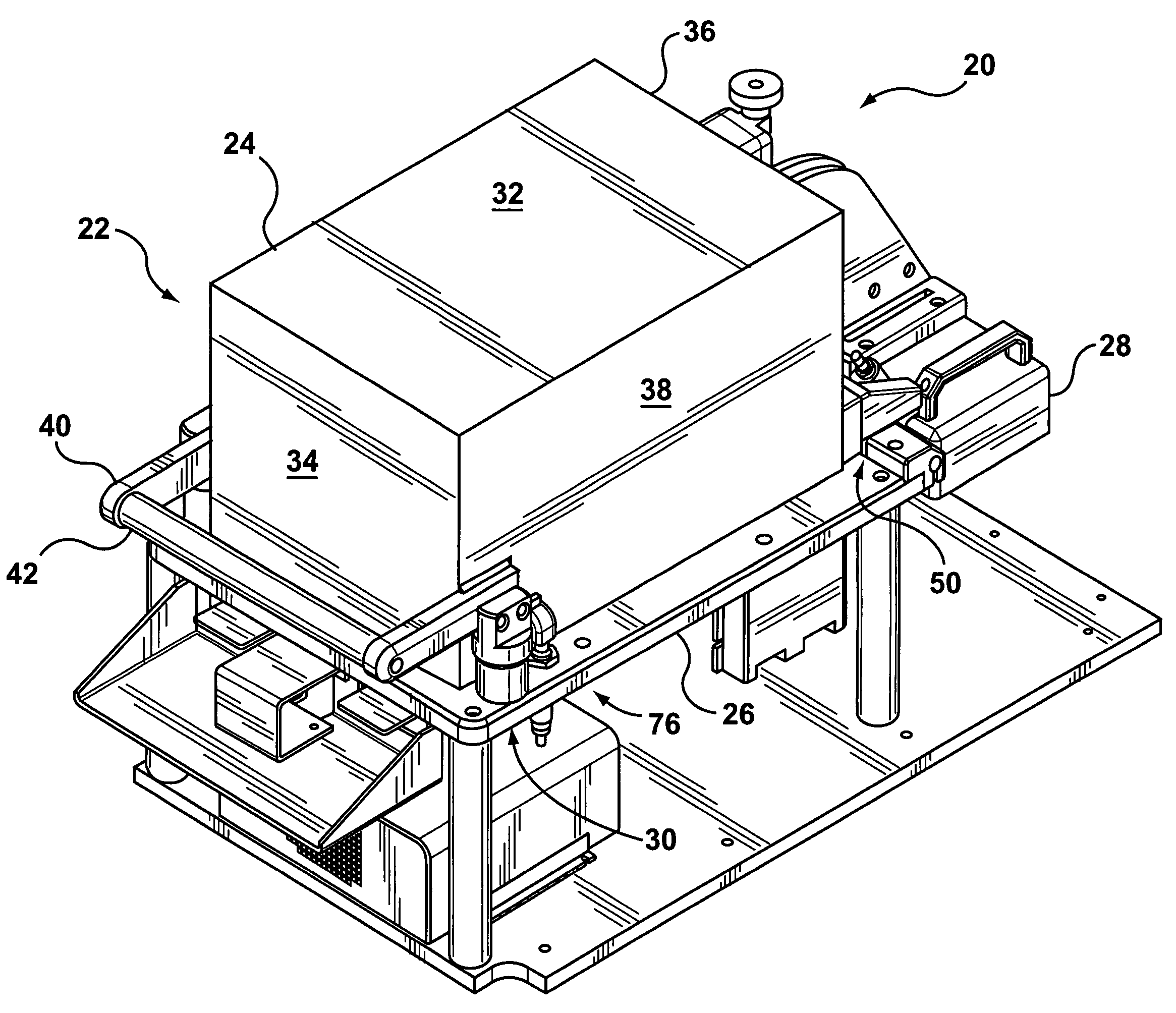
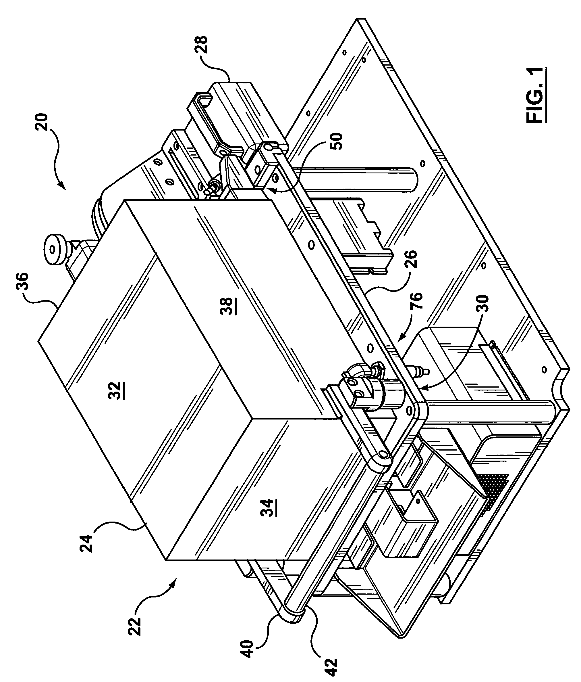
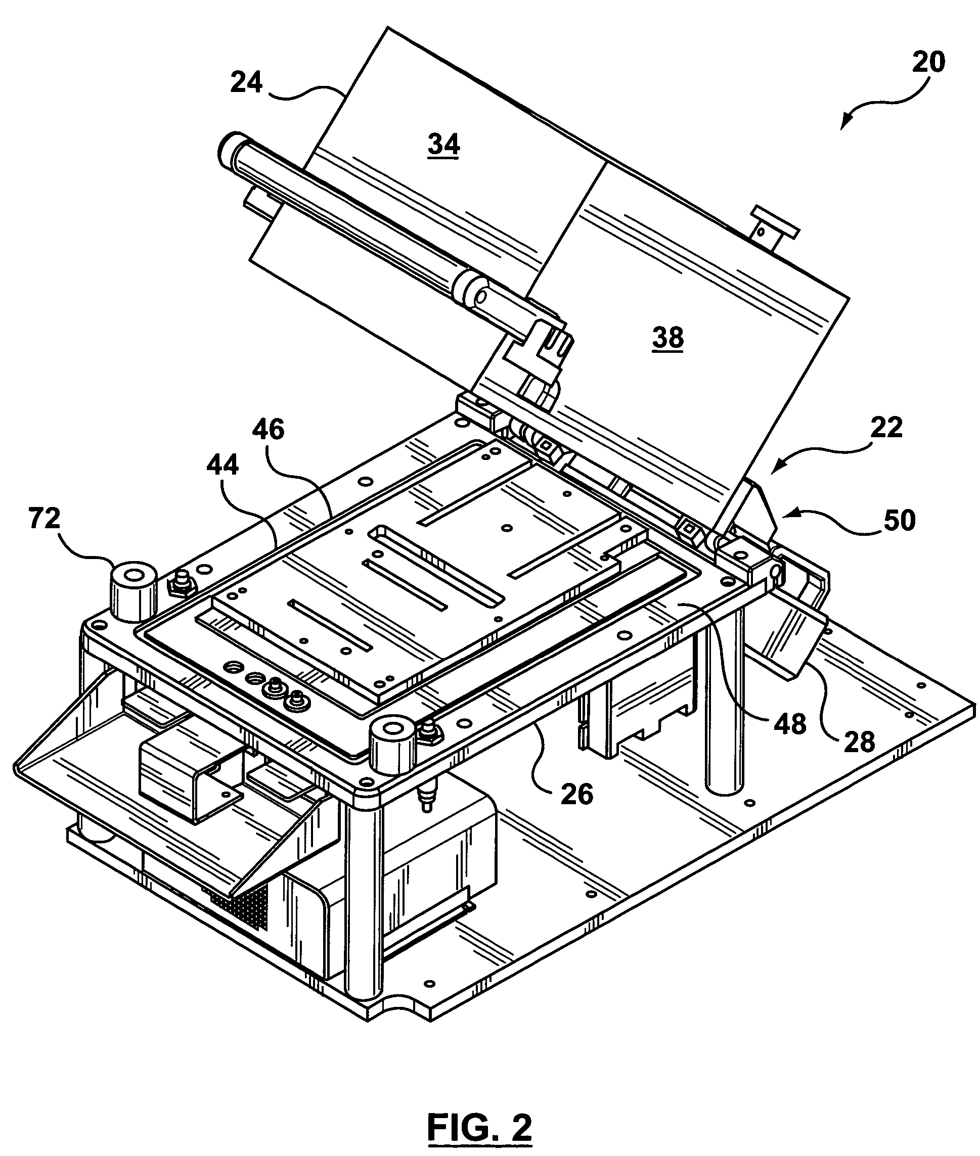
[0021]According to one embodiment of the invention, there is provided an RF isolation container including: an electrically conductive housing, including a lid hingedly connected to a base such that the lid can be moved between an open position and a closed position; a counterweight provided to the housing such that the lid is biased to be in the open position; and a locking mechanism provided to the housing to lock the lid to the base when in the closed position. The counterweight allows the lid to open automatically following a test and also allows the lid to be moved by an operator with very little force.

[0022]In a particular case, the locking mechanism is an electromagnet locking mechanism including: an electromagnet provided to one of the lid and the base; and a strike provided to the other of the lid and the base, such that when the lid is being closed, the strike comes into an electromagnetic field generated by the electromagnet and is drawn to and held by the electromagnet su...


PUM


Abstract

An RF isolation container that includes a counterweight system to assist an operator with opening and closing operations, an electromagnet locking mechanism for easier and consistent locking of the RF isolation container and a motion damping mechanism to relieve fatigue on operating components and on human operators.

Description

FIELD OF THE INVENTION[0001]The invention generally relates to radio frequency (RF) isolation containers, and, more particularly relates to an RF isolation container that includes a counterweight, electromagnetic locking mechanism and / or motion dampers.BACKGROUND OF THE INVENTION[0002]Radio frequency (RF) isolation containers are used to test the operation of equipment in an isolated environment where the equipment will not be affected by external radio frequency interference. In a particular case, the RF isolation container may also include internal damping of RF waves so that the equipment will not be affected by reflected RF waves generated by the operation of the equipment itself.[0003]A conventional RF isolation container generally includes a cast or welded rectangular housing that is divided into a top portion and a bottom portion. The top portion and the bottom portion are connected by a hinge at one end thereof. The bottom portion typically has walls with a grooved joint run...

Claims


Application Information

Patent Timeline
Patent Type & Authority Patents(United States)
IPC IPC(8): H05K9/00G01R31/02
CPCH05K9/0007G01R29/0821
Inventor MOK, WINSTONKOCH, ALEXANDERIVANNIKOV, ARKADY
Owner MALIKIE INNOVATIONS LTD
Why Eureka
Try Eureka