Image forming apparatus with cleaning device for removing remaining toner from outer surface of photosensitive member

a technology of cleaning device and photosensitive drum, which is applied in the direction of electrographic process apparatus, corona discharge, instruments, etc., can solve the problems of difficulty in uniform charging of unusable substances will be removed, and non-uniformity of charge on the outer peripheral surface of the photosensitive drum, so as to effectively prevent the occurrence of charge non-uniformity and reliably avoid image non-uniformity

Inactive Publication Date: 2008-07-01
KYOCERA DOCUMENT SOLUTIONS INC
View PDF13 Cites 9 Cited by
  • Summary
  • Abstract
  • Description
  • Claims
  • Application Information

AI Technical Summary

Benefits of technology

[0011]It is an object of the present invention to provide an image forming apparatus capable of suppressing the occurrence of charge nonuniformity in an outer peripheral surface of a photosensitive member even if an extraneous substance is attached onto an outer peripheral surface of a charge roller.
[0012]Through various researches on the cause of charge nonuniformity occurring in a surface of a photosensitive member, the present invention has been accomplished based on clarification of a mechanism of occurrence thereof. Heretofore, it has been considered that charge nonuniformity is caused by submicron-order additive particles, specifically an extraneous substance mixed in toner particles, such as silica and titanium, which has slipped through a clearance between a blade of a cleaning device and the surface of the photosensitive member and remained thereon without being removed, and then attached onto the surface of the charge roller. As the result of various experimental tests, the inventor found that, even if an extraneous substance is attached onto the outer peripheral surface of the charge roller, as long as the extraneous substance is uniformly attached thereonto, discharge stability in the charge roller can be maintained without occurrence of charge nonuniformity in the outer peripheral surface of the photosensitive member.
[0015]After the transfer process, the surface of the photosensitive member is subjected to a cleaning process based on a given cleaning device. Then, the cleaned surface of the photosensitive member is applied with the voltage of the same polarity as that of the voltage in the charge roller, from the preliminary voltage-applying member which is being reciprocated in two directions which are orthogonal to the movement direction of the surface of the photosensitive member, and parallel to the surface of the photosensitive member, by the reciprocating mechanism. In this way, before a voltage is re-applied by the charge roller, the cleaned surface of the photosensitive member is subjected to the preliminary charge process. Thus, even if a transfer memory of opposite-polarity charges is formed and left on the cleaned surface of the photosensitive member, the preliminary voltage-applying member can counteract the transfer memory. Subsequently, the surface of the photosensitive member is subject to a charge erasing process based on the charge erasing device, and then uniformly re-charged by the charge roller to perform the next image forming job.
[0016]As above, the preliminary voltage-applying member is reciprocated along the surface of the photosensitive member and in a direction orthogonal to the movement direction of the surface of the photosensitive member, by the reciprocating mechanism. Thus, even if the surface of the photosensitive member has an extraneous substance attached thereon, the extraneous substance is uniformly spread over the surface of the photosensitive member according to the reciprocating movements. That is, even if the uniformly-spread extraneous substance on the surface of the photosensitive member reaching an outer peripheral surface of the charge roller is attached onto the outer peripheral surface of the charge roller, the attached extraneous substance will be uniformly distributed over the outer peripheral surface of the charge roller. Therefore, the surface of the photosensitive member subjected to the charge process through contact with the charge roller can be uniformly charged. This makes it possible to effectively prevent the occurrence of charge nonuniformity in the surface of the photosensitive member so as to reliably avoid image nonuniformity due to the charge nonuniformity.

Problems solved by technology

According to this technique, even if residual toner particles and fine additive particles which have not been able to be removed from the outer peripheral surface of the photosensitive drum by the cleaning device are attached on the outer peripheral surface of the charge roller, these undesirable substances will be removed by the brush roller.
Even using the technique disclosed in the document D1, the charge roller cannot remove such a transfer memory, and a problem about charge nonuniformity occurring in the outer peripheral surface of the photosensitive drum still remains.
Consequently, electrical characteristics of an outer peripheral surface of the primary charge roller become uneven to cause difficulty in uniformly charging the outer peripheral surface of the photosensitive drum.
Thus, a problem about inability to reliably eliminate charge nonuniformity in the outer peripheral surface of the photosensitive drum still remains.

Method used


Image

  • Image forming apparatus with cleaning device for removing remaining toner from outer surface of photosensitive member
  • Image forming apparatus with cleaning device for removing remaining toner from outer surface of photosensitive member
  • Image forming apparatus with cleaning device for removing remaining toner from outer surface of photosensitive member

Examples


Embodiment Construction

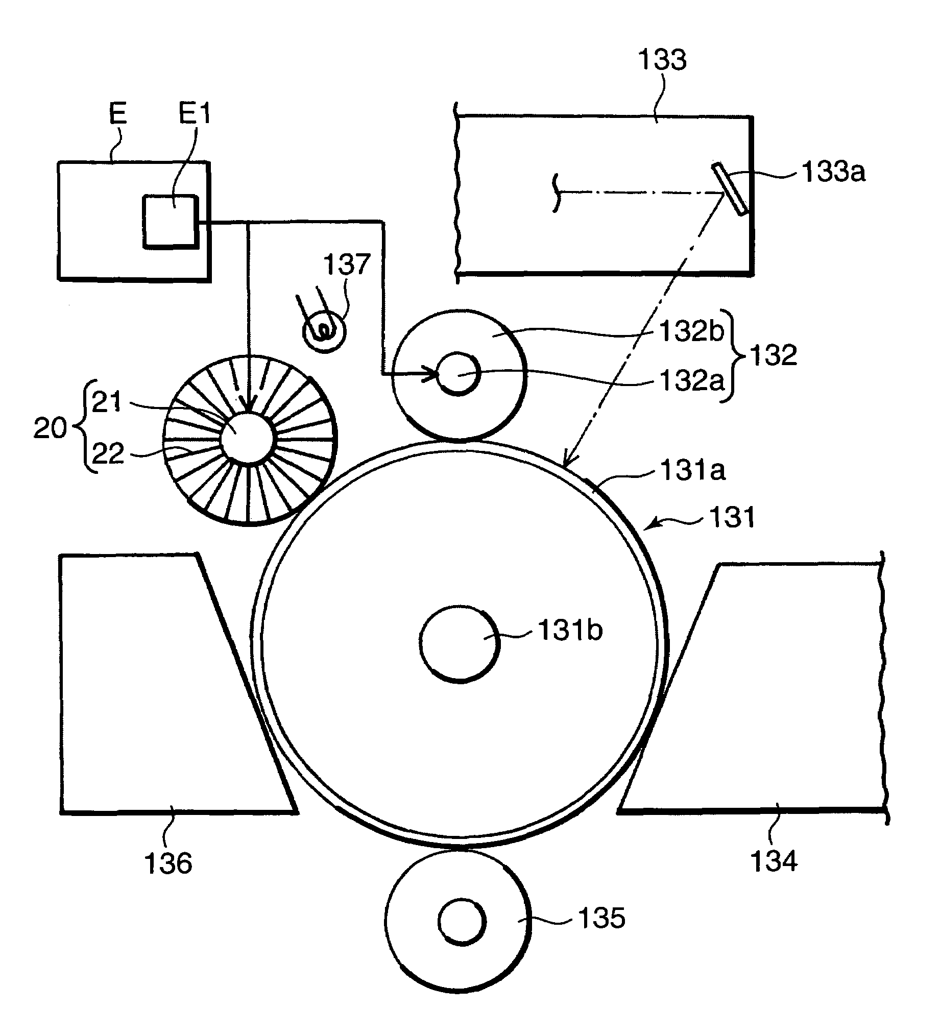
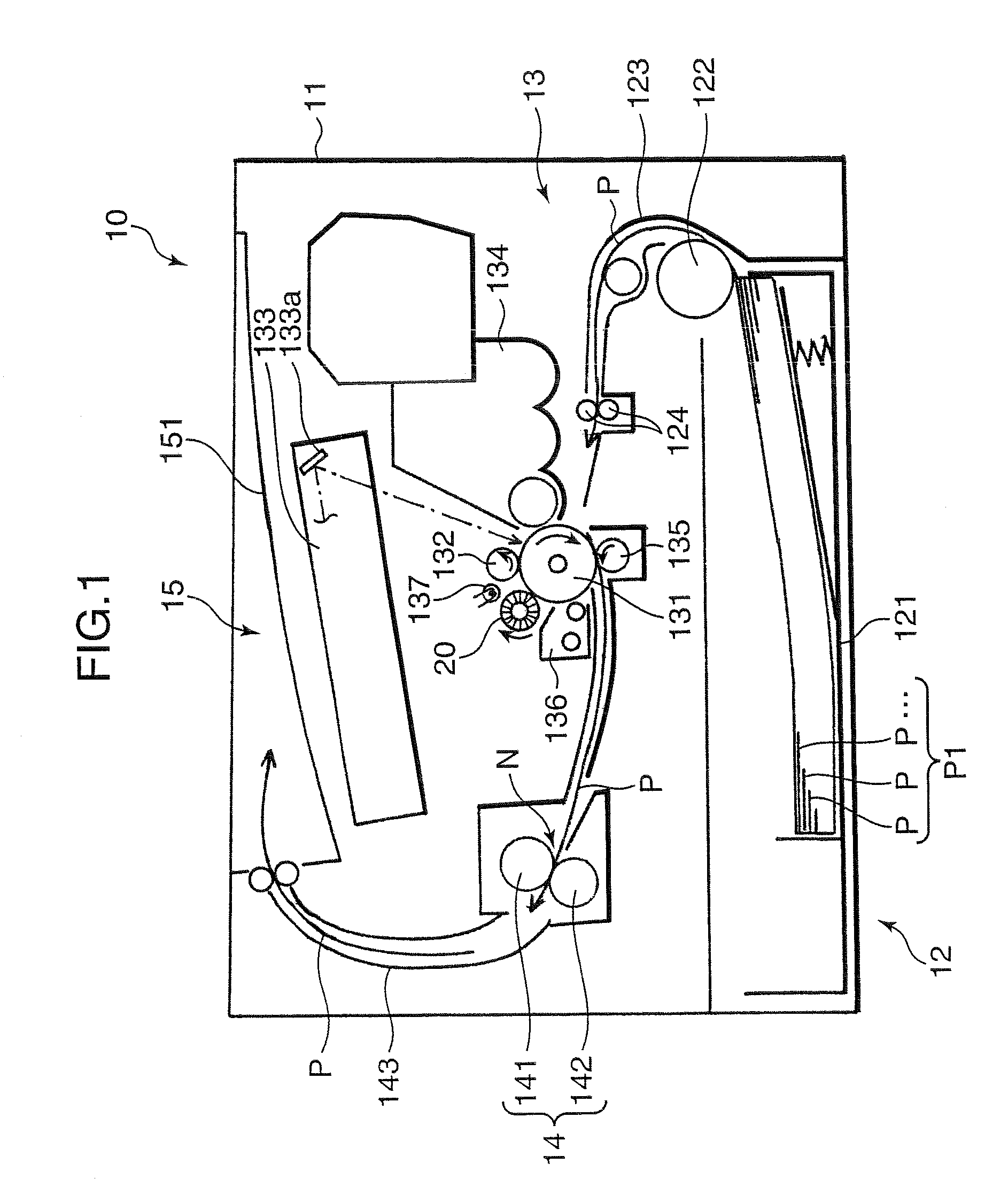
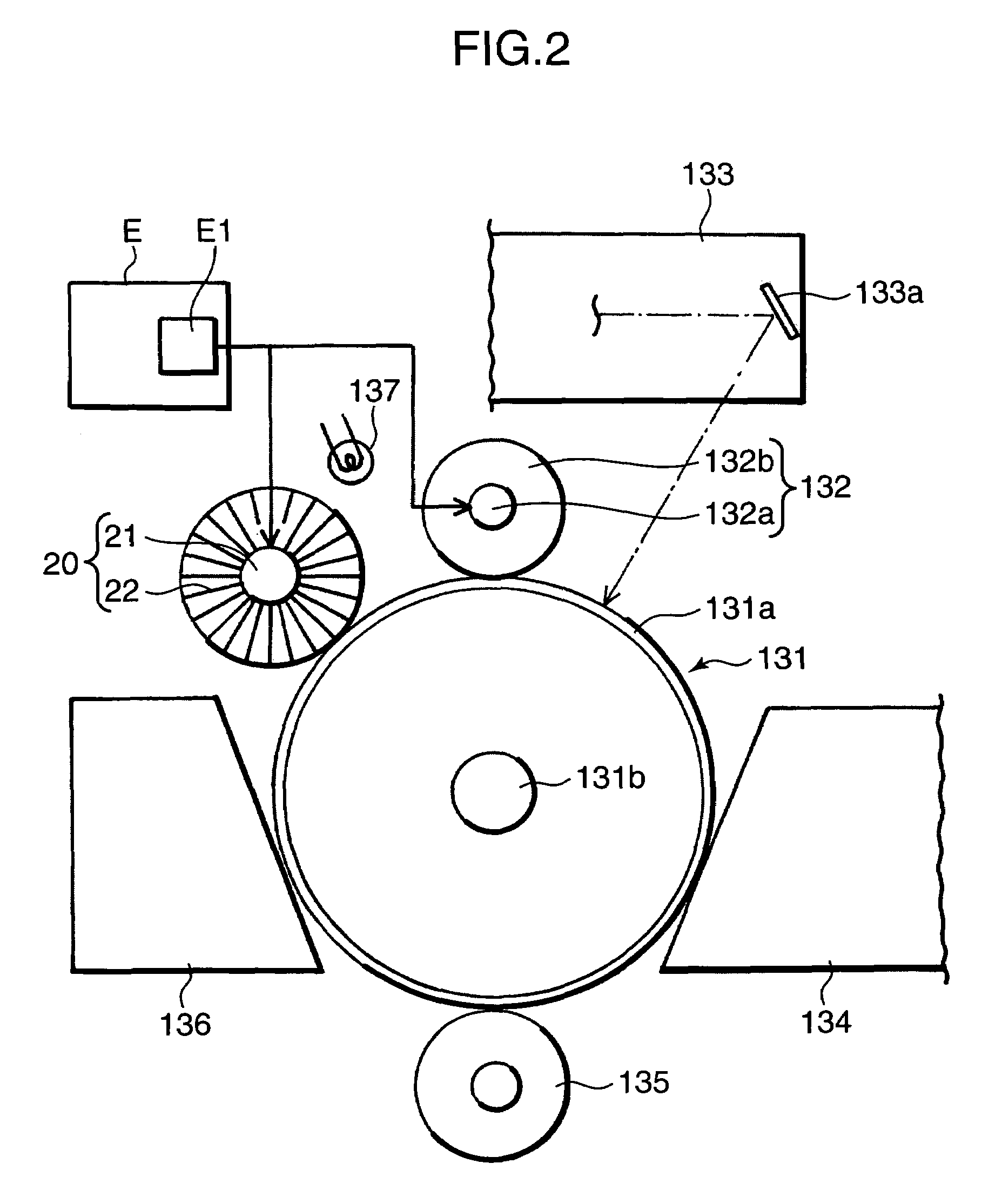
[0023]FIG. 1 is an explanatory sectional front view showing an internal structure of a printer as an image forming apparatus according to one embodiment of the present invention. As shown in FIG. 1, the printer (image forming apparatus) 10 comprises: an apparatus body 11 which is internally provided with a sheet storage section 12 for storing a stack of sheets (transfer targets) P as an object of a printing job, a transfer section 13 for subjecting each of the sheets P fed from the sheet stuck P1 stored in the sheet storage section 12, to an image transfer process, and a fixing section 14 for subjecting the sheet P after being subjected to the transfer process based on the transfer section 13, to a fixing process; and a sheet receiving section 15 formed at a top portion of the apparatus body 11 to receive the sheet P after being subjected to the fixing process based on the fixing section 14.

[0024]The sheet storage section 12 includes a given number (one in this embodiment) of sheet ...


PUM


Abstract

An image forming apparatus has a charge roller, a charge erasing device and a preliminary voltage-applying member disposed around a rotationally movable photosensitive member. The charge roller subjects a surface of the photosensitive member to a charge process while contacting the surface of the photosensitive member. The charge erasing device is on an upstream side of the photosensitive member relative to the charge roller and erases the charged area in the photosensitive member. The preliminary voltage-applying member is on an upstream side of photosensitive member relative to the charge erasing device and applies to the surface of the photosensitive member a voltage of the same polarity as the voltage applied from the charge roller to the surface, while contacting the surface. The preliminary voltage-applying member is reciprocated along the surface of the photosensitive member and in a direction orthogonal to the movement direction of the surface.

Description

BACKGROUND OF THE INVENTION[0001]1. Field of the Invention[0002]The present invention relates to an image forming apparatus suitable as a copying machine, a facsimile machine or a printer.[0003]2. Description of the Related Art[0004]Heretofore, there has been known an image forming apparatus as disclosed in Japanese Patent Laid-Open Publication No. 04-60660 (hereinafter referred to as “document D1”). This image forming apparatus is designed to apply a bias voltage through a charge roller to an outer peripheral surface of a photosensitive drum which is being rotated about a given drum shaft so as to electrostatically charge the outer peripheral surface uniformly. Then, a laser beam generated based on image information is emitted onto the uniformly-charged outer peripheral surface of the photosensitive drum to eliminate a part of the uniformly charged area so as to form an electrostatic latent image. Toner particles are then supplied to the electrostatic latent image to form a toner i...

Claims


Application Information

Patent Timeline
Patent Type & Authority Patents(United States)
IPC IPC(8): G03G15/02G03G21/00
CPCG03G21/08
Inventor TANAKA, NARIAKI
Owner KYOCERA DOCUMENT SOLUTIONS INC
Why Eureka
Try Eureka