Vehicle lamp

a technology for lamps and vehicles, applied in the field of lamps for vehicles, can solve the problems of difficult to efficiently guide the light, high output, and difficult to diffuse light, and achieve the effects of reducing the incidence of non-uniform luminance, efficiently guiding the light, and avoiding the influence of heat emitted by the light source on the light guide pla

Active Publication Date: 2017-09-28
STANLEY ELECTRIC CO LTD
View PDF13 Cites 7 Cited by
  • Summary
  • Abstract
  • Description
  • Claims
  • Application Information

AI Technical Summary

Benefits of technology

[0034]In the above-mentioned configuration, a high output light source can be used and influence of heat emitted from the light source on the light guide plate can be avoided.
[0035]According to the aspect of the present invention, it is possible to provide the vehicle lamp capable of efficiently guiding the light from the light source into the light guide plate, and further, suppressing occurrence of luminance (emission) nonuniformity.

Problems solved by technology

However, while an LED has high directivity (straightness), the light is not easily diffused.
Accordingly, the more the thickness of the light guide plate is reduced, the more difficult it becomes to guide the light efficiently while repeatedly reflecting the light from the light source inside the light guide plate.
In addition, high output LEDs such as vehicle lamps are not used for a light source for a lighting device.

Method used


Image

  • Vehicle lamp
  • Vehicle lamp
  • Vehicle lamp

Examples


Embodiment Construction

[0047]Hereinafter, an embodiment of the present invention will be described in detail with reference to the accompanying drawings.

[0048]Further, in the drawings used in the following description, different dimensional scales of the components may be shown so that the components can be easily seen, and the dimensional ratios and the like of the components are not always shown as same in reality.

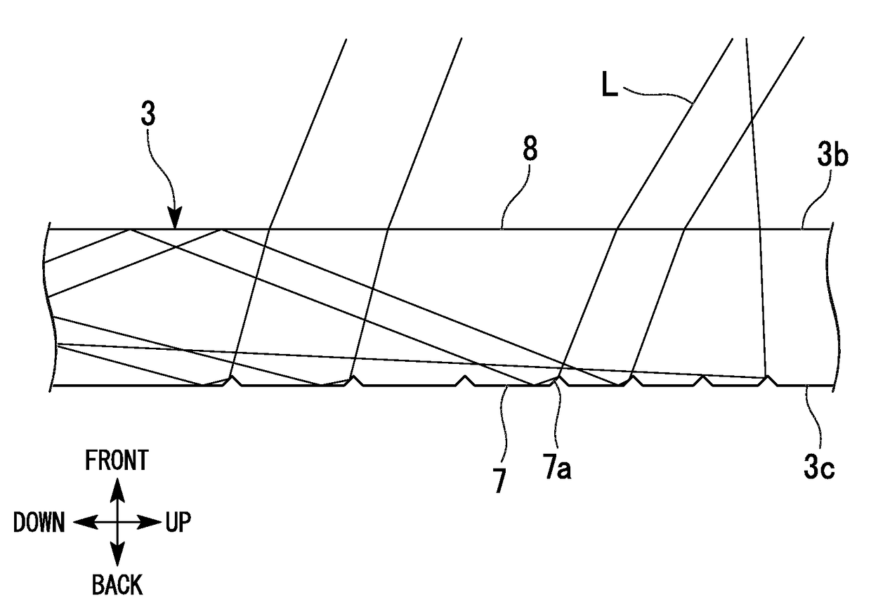
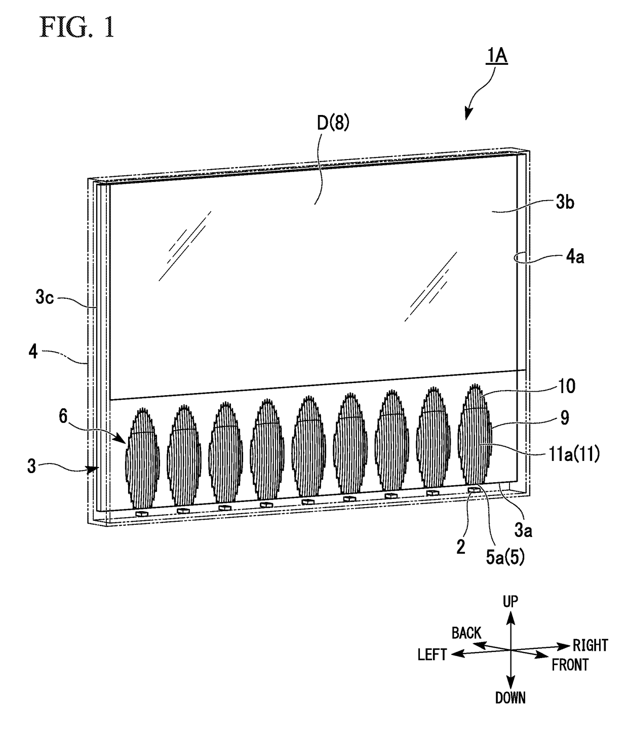
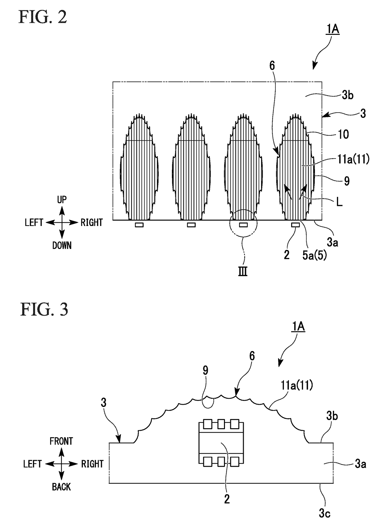
[0049]As an embodiment of the present invention, for example, a vehicle lamp 1A shown in FIGS. 1 to 5 will be described. Further, FIG. 1 is a perspective view showing the exterior of the vehicle lamp 1A. FIG. 2 is a plan view of a major part showing a configuration of the vehicle lamp 1A. FIG. 3 is an enlarged end view of an enclosed portion III shown in FIG. 2. FIG. 4 is a light path diagram showing a configuration of the vehicle lamp 1A. FIG. 5 is an enlarged light path diagram showing an enclosed portion V shown in FIG. 4.

[0050]As shown in FIG. 1 to FIG. 5, the vehicle lamp 1A of the embodi...


PUM


Abstract

A vehicle lamp includes a plurality of light sources and a light guide plate, the plurality of light sources are disposed in parallel along one end surface of the light guide plate, the light guide plate has a light reflection section formed at a first surface of the light guide plate and configured to reflect light entered from the one end surface toward a second surface of the light guide plate, the light reflection section includes a plurality of parabolic reflection surfaces, and the parabolic reflection surfaces protrude from the first surface and have shapes curved along a direction in which the light entering from the one end surface advances and a direction crossing with the direction in which the light entering from the one end surface advances.

Description

CROSS-REFERENCE TO RELATED APPLICATION[0001]Priority is claimed on Japanese Patent Application No. 2016-059947, filed Mar. 24, 2016, the content of which is incorporated herein by reference.BACKGROUND[0002]Field of the Invention[0003]The present invention relates to a vehicle lamp.[0004]Description of Related Art[0005]In the related art, as a vehicle lamp mounted on a vehicle, a lamp in which a light source such as a light emitting diode (LED) or the like and a plate-shaped light guide member (a light guide plate) are combined is known (for example, see Japanese Unexamined Patent Application, First Publication No. 2012-169116 and Japanese Unexamined Patent Application, First Publication No. 2006-93104).[0006]The light guide plate allows light emitted from the light source to enter from one end surface (an incident surface), reflects the light by using a plurality of reflection cuts formed at one main surface (a reflection surface), and then allows the light to exit from the other ma...

Claims


Application Information

Patent Timeline
Patent Type & Authority Applications(United States)
IPC IPC(8): F21S8/10B60Q1/30
CPCF21S48/2243F21S48/234F21S48/2212F21Y2115/10B60Q1/30F21Y2113/13F21S48/215G02B6/002F21Y2103/10F21S43/14F21S43/239F21S43/241F21S43/243F21S43/249G02B6/0016G02B6/0068F21S43/26F21S43/31
Inventor KAWABATA, MARI
Owner STANLEY ELECTRIC CO LTD
Why Eureka
Try Eureka