
Electronic percussion instrument, system and method with rim shot detection

a technology detection methods, applied in the field can solve the problems of no disclosure in patent reference 2 and high cost of electronic percussion instruments, and achieve the effects of simple and inexpensive circuit configuration, and reliable detection

Active Publication Date: 2008-07-08
ROLAND CORP
View PDF3 Cites 22 Cited by
  • Summary
  • Abstract
  • Description
  • Claims
  • Application Information

AI Technical Summary

Benefits of technology

The present invention relates to an electronic percussion instrument that can detect and generate a musical tone based on the performance method of the instrument. The instrument has input means for detecting the vibration of the head section and rim section, and a control system that can generate a musical tone based on the size of the vibration of the head section and rim section. The control system can also detect the leading edge polarity of the vibration of the head section and generate a musical tone based on the polarity of the leading edge. The instrument can reliably detect which performance method has been performed and can generate a musical tone that is appropriate for the detected performance method. The instrument is simple and inexpensive to manufacture and can be easily detected with existing sensors. The technical effects of the invention include improved accuracy in detecting the performance method and the ability to generate a musical tone that is appropriate for the detected performance method.

Problems solved by technology

Thus, there is the problem that the cost of the electronic percussion instrument becomes high.
Also, there are the problems that the performer must carry out the performance by differentiating between the two switches and the performance methods are constrained.
However, there is no disclosure in Patent Reference 2 as to the generation of a variety of musical tones that conform to performance methods, such as an open rim shot or a closed rim shot, in accordance with the striking force that has been detected.

Method used


Image

  • Electronic percussion instrument, system and method with rim shot detection
  • Electronic percussion instrument, system and method with rim shot detection
  • Electronic percussion instrument, system and method with rim shot detection

Examples


Embodiment Construction

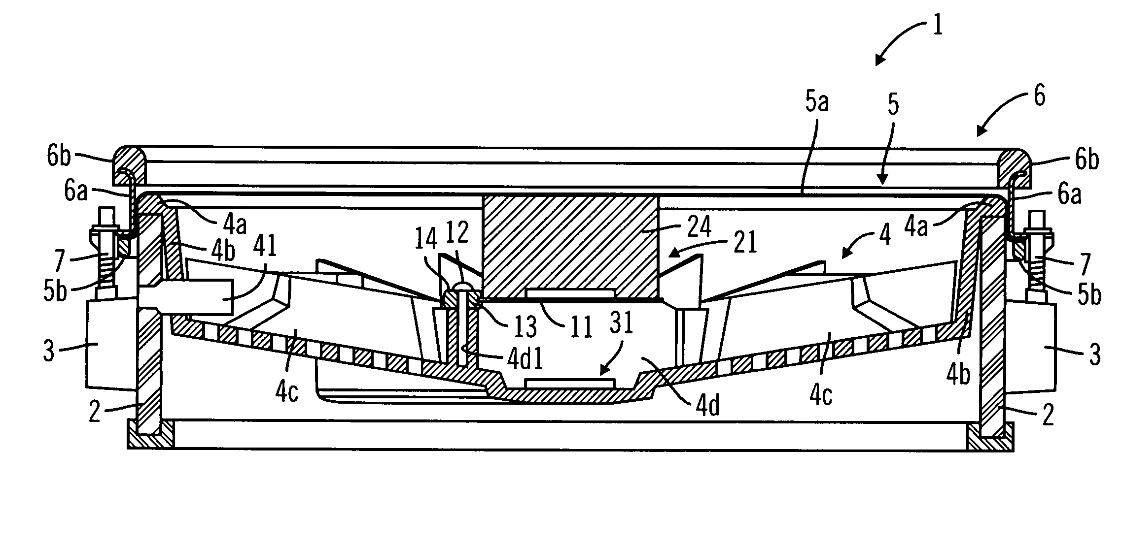
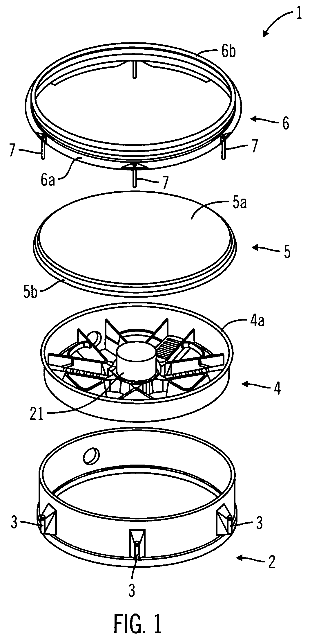
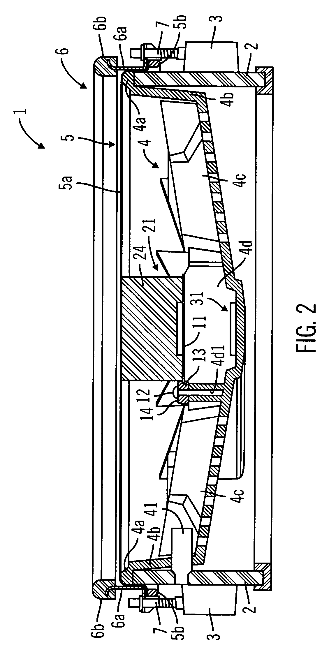
[0036]Explanations will be given below regarding embodiments of the present invention while referring to the attached drawings. First, an explanation will be given regarding a striking detection section 1 of an electronic percussion instrument in accordance with an embodiment of the invention, while referring to FIGS. 1-3. FIG. 1 is a disassembled oblique view drawing of the striking detection section 1. FIG. 2 is a cross-section drawing of a case in which the striking detection section 1, which is in an assembled state, has been cut on a vertical surface that passes through the center of the striking detection section 1. FIG. 3 is a drawing that shows a configuration of a head sensor in detail.

[0037]An electronic percussion instrument of an embodiment, known as a so-called “electronic drum” or “electronic pad” that employs a stick and the like for striking, comprises the striking detection section 1. The striking detection section 1 is furnished with a sensor with which the vibrati...


PUM


Abstract

An electronic percussion instrument includes input means, comparison means, and musical tone generation control means. The input means allows for the input of a vibration of a head section and a vibration of a rim section that have been detected by a striking detection section. The comparison means allows for a comparison of a size of the vibration of the head section and a size of the vibration of the rim section. The musical tone generation control means allows for controlling a generation of a musical tone based on a result of a comparison by the comparison means such that the musical tone corresponds either to the vibration of the head section or to the vibration of the rim section. In those cases where the musical tone corresponds to the vibration of the rim section, the generation of the musical tone can be further controlled.

Description

CROSS-REFERENCE TO RELATED PATENT APPLICATIONS[0001]Japan Priority Application 2004-002787, filed Jan. 08, 2004 including the specification, drawings, claims, and abstract, is incorporated herein by reference in its entirety.BACKGROUND OF THE INVENTION[0002]1. Field of the Invention[0003]Embodiments of the present invention relate to an electronic percussion instrument and, in particular embodiments, to an electronic percussion instrument with which a musical tone is generated in conformance with output of sensors that are respectively disposed on a head and a rim.[0004]2. Related Art[0005]In a performance with an acoustic drum, in addition to the usual performance in which only the striking surface (the head) is struck, it is possible to broaden the scope of the performance by the so-called rim shot performance method. For the rim shot, there are, in general, two types of performance methods: (i) the open rim shot in which the rim and the striking surface (the head) are struck at t...

Claims


Application Information

Patent Timeline
Patent Type & Authority Patents(United States)
IPC IPC(8): G10H1/00G10D13/02G10H1/06G10H3/14
CPCG10H3/146G10H2230/301G10H2220/525
Inventor SUSAMI, RYO
Owner ROLAND CORP
Learn More