Device to secure shoe laces

a technology for shoe laces and devices, applied in the field of shoe laces, can solve the problems of shoe laces shoe laces are still susceptible to coming untied, and untied laces can have extreme consequences

Inactive Publication Date: 2008-07-15
MILLER III JOHN T
View PDF11 Cites 7 Cited by
  • Summary
  • Abstract
  • Description
  • Claims
  • Application Information

AI Technical Summary

Problems solved by technology

Keeping shoe laces tied has been a problem since shoe laces were introduced.
Many people have resorted to tying shoe laces using double knots but the laces are still susceptible to coming untied.
However, the majority of shoes still use common laces that come untied.
An untied shoe lace is a tripping hazard and in hazardous occupations such as law enforcement, fire fighting and the military; untied laces can have extreme consequences.
Athletes and children are particularly susceptible to having their shoe laces come untied.
The shortcomings of the prior art are bulkiness, complexity, modifying the conventional tying method, multiple parts, appealing only to children, questionable effectiveness and difficulty in latching and unlatching.
Some of the prior art has questionable effectiveness as evidenced by their use of elastic bands for the tension method.
Over time, they will lose their elasticity.
The method of using the contact of an elastic band against the lace as a means of holding is not as effective as gripping teeth.
This keeps the tension on the laces of the shoe constant but does not address the bow coming untied which is the larger problem.
It only retains the bow and loose string end and doesn't secure the part of the lace that keeps the tension on the shoe.
Some use a combination of the three resulting in an expensive and complex device to construct.
Some of the previous designs are very large and intrusive to the wearer.
It would limit the commercial appeal of having something so large and complex on a shoe.
The designs that show clowns, bears, turtules, alligators, etc. in their drawings for decorative purposes would be very cumbersome and distracting to the wearer.
Some of the previous designs are completely oriented toward kids and would not have broad appeal for adults.
Some of the prior art are easy to install and some are quite complicated.
The elastic bands lose tension over time and do not grip as well as a toothed design.
The device consisting of two small clamps would be difficult or impossible to latch over large, round laces and require two clamping devices to be separately attached to the laces instead of one making this device inconvenient to use.

Method used


Image

  • Device to secure shoe laces
  • Device to secure shoe laces
  • Device to secure shoe laces

Examples


Embodiment Construction

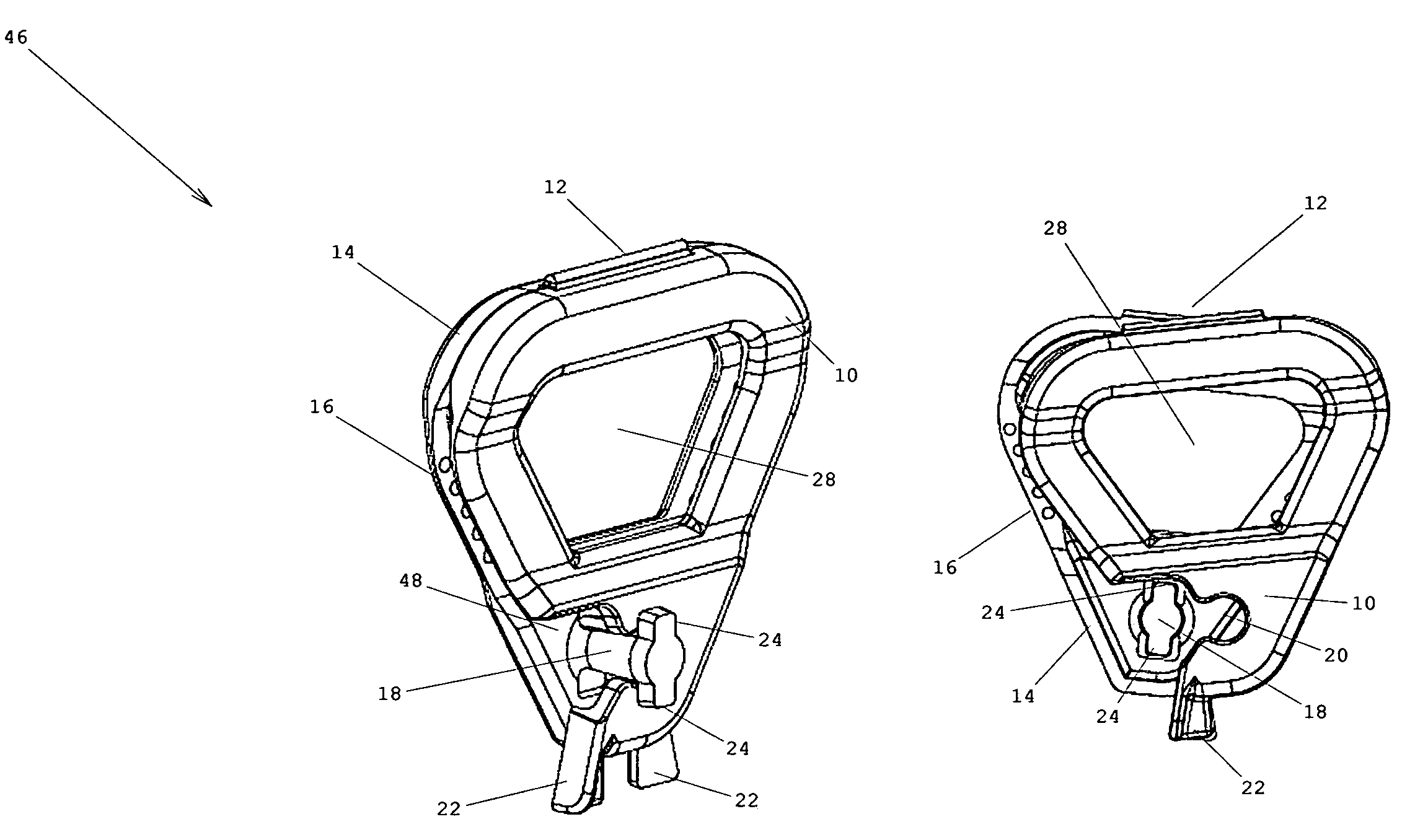
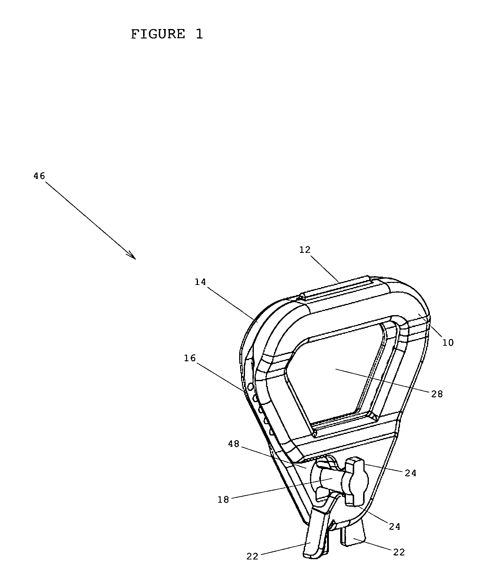
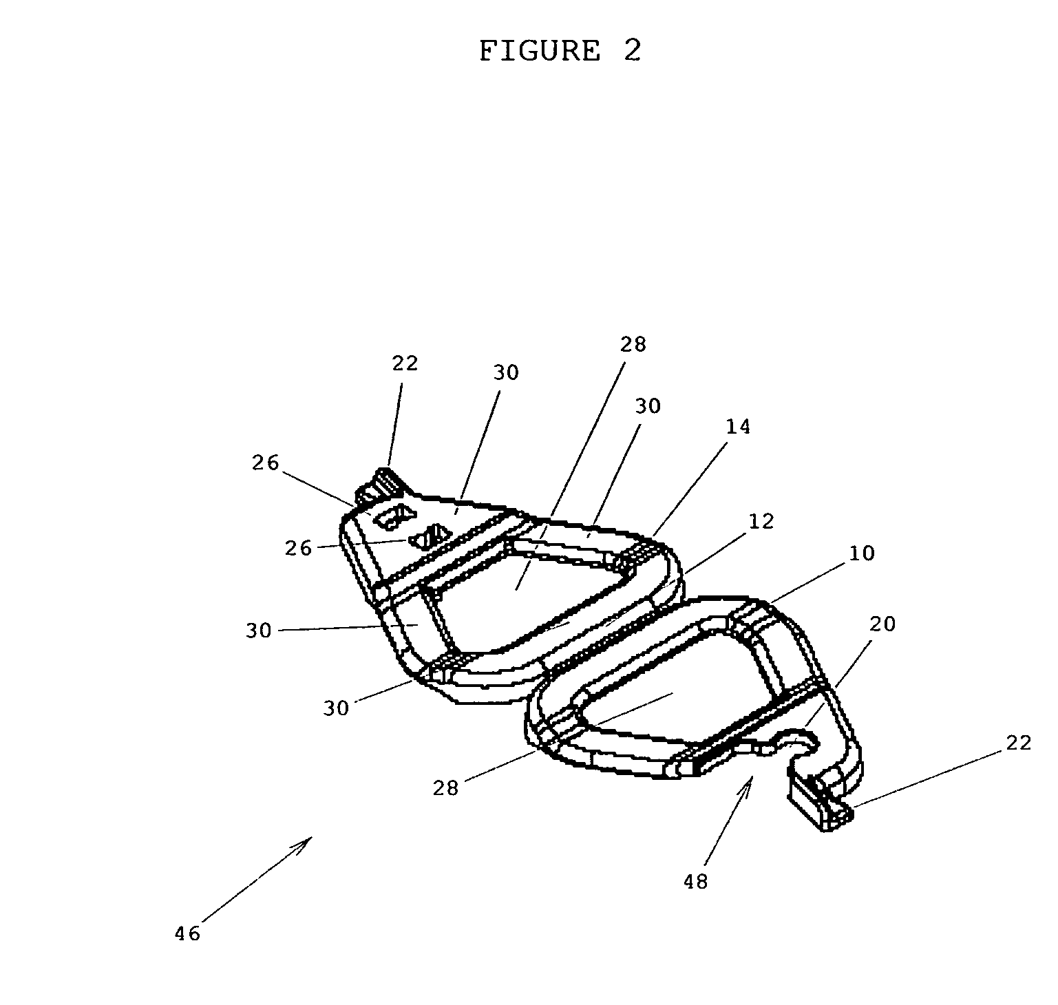
[0037]The clamping device for keeping conventionally tied shoe 32 laces from coming untied consists of a top frame 14 and a bottom frame 10 that is slid under and over the lace knot 34 and latched together. The lace knot 34 is now secure. The lace knot 34 remains tied until the wearer is ready to remove their shoes at which time they simply unlatch and separate the two frames from around the knot. This device does not stay with the shoe 32 but can be transferred to other shoes.

[0038]FIG. 1 is a bottom perspective view showing the device in the latched position. The device will hereafter be referenced as the grip 46. The grip 46 comprises a top frame 14 and a bottom frame 10 connected by a hinge 12. The grip 46 is opened by squeezing the unlatching tabs 22 horizontally toward each other allowing the two frames 10 and 14 to be pulled vertically apart. The bottom frame 10 is pushed under a conventionally tied lace knot 34 and the top frame 14 goes over the lace knot 34 with the grippin...


PUM


Abstract

A clamping device for keeping conventionally tied shoe laces from becoming untied. The device has a top frame that contacts the top of the shoe laces and a bottom frame that contacts the bottom of the shoe laces. These two frames clamp the lace on both sides of a conventionally tied shoe lace knot and are connected by a hinge. The two frames are secured together by a latch. This device secures both the lace tension on the shoe and the knot.

Description

RELATED APPLICATIONS[0001]This patent application incorporates by reference to Invention Disclosure Document number 592606 dated Jan. 3, 2006 entitled Shoe Lace Grip.FIELD OF THE INVENTION[0002]The present invention relates to shoe laces and, more particularly, to a device that latches around conventionally tied shoe laces to keep the knot from coming untied.BACKGROUND OF THE INVENTION[0003]Keeping shoe laces tied has been a problem since shoe laces were introduced. Many people have resorted to tying shoe laces using double knots but the laces are still susceptible to coming untied. Shoe manufacturers are now introducing alternative forms such as velcro, zipper or elastic bands to keep shoes secure while eliminating the nuisance of untied laces. However, the majority of shoes still use common laces that come untied.[0004]An untied shoe lace is a tripping hazard and in hazardous occupations such as law enforcement, fire fighting and the military; untied laces can have extreme consequ...

Claims


Application Information

Patent Timeline
Patent Type & Authority Patents(United States)
IPC IPC(8): A43C7/00
CPCA43C7/00A43C7/005Y10T24/3705Y10T24/3716
Inventor MILLER, III, JOHN T.
Owner MILLER III JOHN T
Why Eureka
Try Eureka