
Universal trim for recessed lighting

a technology for recessed lighting and trim rings, which is applied in fixed installation, lighting and heating equipment, and support devices for lighting and heating, etc. it can solve the problems of recessed lights that cannot be installed, recessed lights that are expensive and difficult to replace, and the trim rings of one manufacturer cannot fit on the housing of another manufacturer

Inactive Publication Date: 2008-07-15
RAPPAPORT MARGARET
View PDF20 Cites 97 Cited by
  • Summary
  • Abstract
  • Description
  • Claims
  • Application Information

AI Technical Summary

Benefits of technology

"The patent describes a universal trim piece that can be used with different types of recessed lighting fixtures. The trim piece can be made of various materials and has a decorative side with a pattern or texture to provide an aesthetic look. It can be easily installed and removed without replacing the entire housing. The trim piece can be engaged with a trim ring using different types of universal engagement members, such as leaf tabs, magnets, adhesive, fasteners, or compression members. The engagement member can secure the trim piece to the trim ring and can be easily disengaged. The patent also describes a universal trim insert that includes a baffle and a trim piece, which can be inserted into the housing and engaged with the baffle. This allows for easy installation and replacement of the trim piece."

Problems solved by technology

Thus, baffles and trim rings from one manufacturer do not fit on the housing of another manufacturer.
This poses a problem for most users who want to change the look of their recessed lights once the light is installed.
The recessed light installed may not have the new style the user is looking for and the manufacturer may be out of business or does not carry the user's line of recessed light so a user can either get replacement parts or upgrades.
Further, recessed lights are expensive and difficult to replace, typically requiring the ceiling to be torn open to reach the housing.
Thus, a user will experience the same difficulties as above because the user is forced to use Lin's product.
Additionally, a user who did not install Lin's lamp shell cannot use external cover 7.
Thus, although Lin and Wolf disclose trim pieces that are removable, they do not disclose trim pieces that are universal to any recessed light.
Kripp's baffle cannot be retrofitted onto an existing recessed light because rests solely on ring 36 and cannot support its own weight.

Method used


Image

  • Universal trim for recessed lighting
  • Universal trim for recessed lighting
  • Universal trim for recessed lighting

Examples


Embodiment Construction

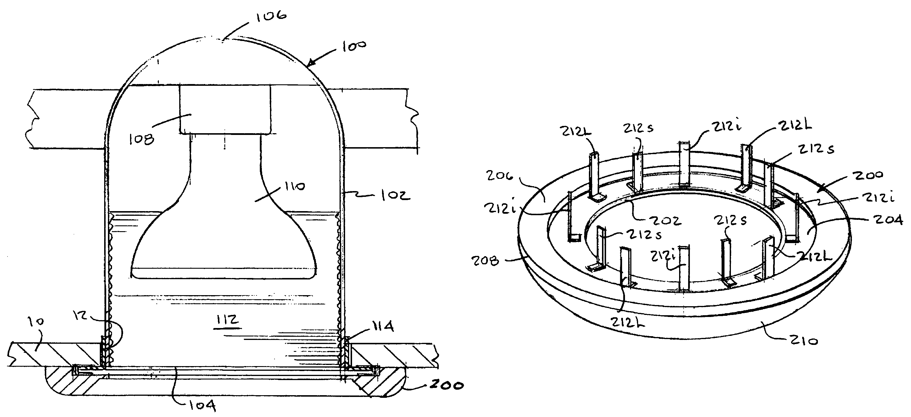
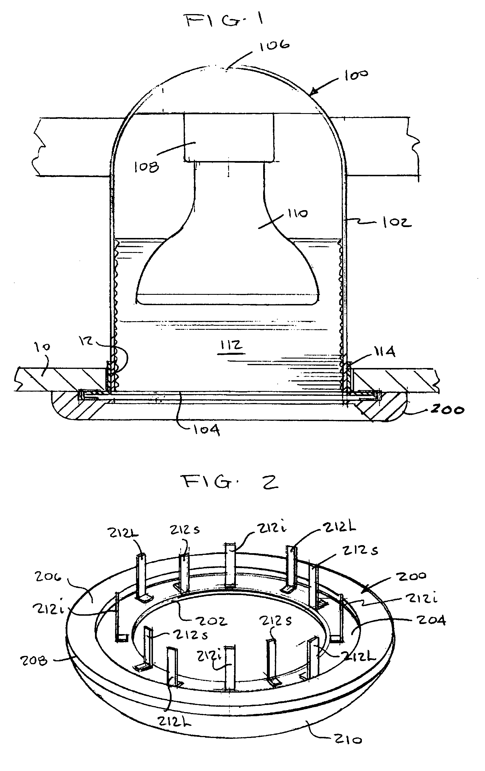
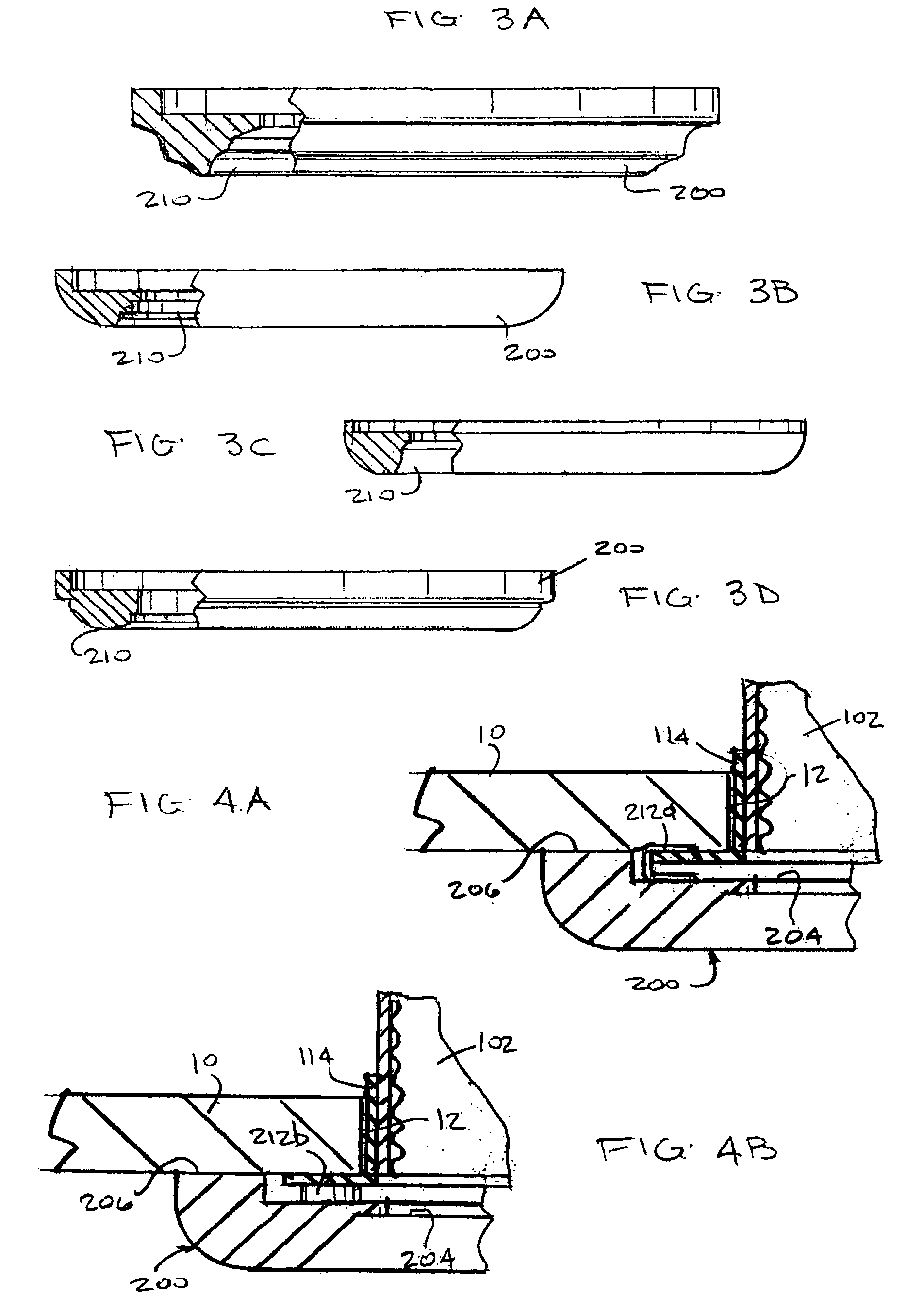
[0055]Referring to FIGS. 1 and 2, universal trim piece 200 for a recessed light 100, according to a preferred embodiment of the present invention, is illustrated. FIG. 1 illustrates a typical recessed light 100 including a housing 102 mounted above or within a ceiling 10 and having an open side 104 and a socket side 106. A lamp socket 108 is mounted to socket side 106, is connected to a power supply (not illustrated), and is positioned to be accessed from open side 104, e.g. to change a lamp 110. Lamp 110 engages lamp socket 108 and lamp socket 108 provides power for lamp 110. Mounted inside housing 102 can be baffle 112. Further, a trim ring 114 is mounted to open side 104 of housing 102 and upon ceiling 10. In the prior art, trim ring 114 is designed as an integrated part of housing 102 and specifically fits a specific housing 102. Trim ring 114 is designed to obscure from view an opening 12 cut through ceiling 10 yet expose open side 104 of housing 102. Note that other recessed l...


PUM


Abstract

A universal trim piece for a recessed light includes a mounting side disposed toward a ceiling and having an aperture sized to conform with a dimension of an open side of a housing for a recessed light. A decorative side is disposed opposite the mounting side and a universal engagement member, disposed on the mounting side, removably engages a trim ring on the recessed light and secure the universal trim piece to the housing and proximate to the ceiling.

Description

BACKGROUND OF THE INVENTION[0001]1. Field of the Invention[0002]The invention relates to electric lighting fixtures, particularly recessed lighting, down light fixtures, and flush mounted fixtures and a designer trim ring that mounts to the exterior of the light fixture regardless of the manufacturer of the fixture.[0003]2. Description of the Related Art[0004]Recessed lights and flush mounted fixtures are standard lighting fixtures in most homes and commercial establishments. Recessed lights are mounted inside of a ceiling and a hole is cut in the ceiling to let the light shine through. A trim ring is used to cover the cut edge of the ceiling and typically lays flush with the ceiling.[0005]Recessed lights are manufactured by many companies, and although most recessed lights seem universal, they are not. There are variations of the size, shape, trim rings, baffles and the means by which the trim rings and baffles engage the housing which is located inside the ceiling. Thus, baffles a...

Claims


Application Information

Patent Timeline
Patent Type & Authority Patents(United States)
IPC IPC(8): F21V17/00F21S8/00F21S8/02F21V3/00F21V17/04F21V17/10F21V17/12
CPCF21S8/02F21V3/00F21V17/04F21V17/12F21V17/105F21V17/108F21V17/101
Inventor RAPPAPORT, MARGARET
Owner RAPPAPORT MARGARET
Learn More