Battery and battery locking unit of mobile terminal

Inactive Publication Date: 2008-07-22
LG ELECTRONICS INC
View PDF9 Cites 2 Cited by
  • Summary
  • Abstract
  • Description
  • Claims
  • Application Information

AI Technical Summary

Benefits of technology

[0016]An object of the invention is to solve at least the above problems and / or disadvantages and to provide at least the advantages described hereinafter.

Problems solved by technology

In addition, in the locking unit, in order to release the locking of the battery, the user has to separate the battery from the body with one hand while pulling the handle portion of the hook, and accordingly it is intricate.

Method used


Image

  • Battery and battery locking unit of mobile terminal
  • Battery and battery locking unit of mobile terminal
  • Battery and battery locking unit of mobile terminal

Examples


Embodiment Construction

[0051]Hereinafter, embodiments of a battery and a battery locking unit of a mobile terminal in accordance with the present invention will be described with reference to accompanying drawings.

[0052]There can be plural embodiments, hereinafter the preferred embodiments will be described.

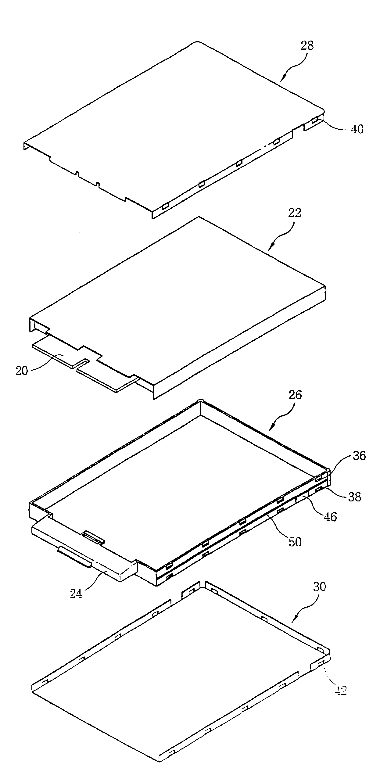
[0053]FIG. 4 is a sectional-perspective view illustrating a mobile terminal in accordance with an embodiment of the present invention. The mobile terminal includes a terminal body 2 at which a circuit substrate is disposed in and various operation buttons for operating the terminal are installed on; a battery 4 attached to the rear of the terminal body 2; a cover 6 detachably installed at the rear of the terminal body 2; and a locking unit 8 installed at the both sides of the cover and locking the cover 6 to the terminal body 2.

[0054]As depicted in FIG. 5, in the terminal body 2, an installation portion 10 for installing the battery 4 is formed at the rear, a supporting protrusion 12 is formed at the b...


PUM


Abstract

In a battery locking unit of a mobile terminal capable of increasing space usability of a terminal body and simplifying battery detachment operation by installing a battery locking unit on a cover, the locking unit consists of a battery installed at the rear of a terminal body; a cover attached/detached to/from the rear of the rear body by a sliding method and protecting the battery; and a locking unit installed at a certain side of the cover, locking the cover to the terminal body by restricting the sliding movement of the cover and releasing the locking of the cover by a pressing operation of a user.

Description

BACKGROUND OF THE INVENTION[0001]Pursuant to 35 U.S.C. § 119(a), this non-provisional patent application claims the priority benefit of Korean Patent Application No. 10-2002-0019761, filed on Apr. 11, 2002 and Korean Patent Application No. 10-2002-0029264, filed on May 27, 2002, the entire contents of which are hereby incorporated by reference.[0002]1. Field of the Invention[0003]The present invention relates to a battery and a battery locking unit of a[0004]mobile terminal, and in particular to a battery and a battery locking unit of a mobile terminal capable of detaching / attaching a battery from / to a terminal body easily and increasing space usability of a mobile terminal.[0005]2. Background of the Related Art[0006]FIG. 1 is a front view illustrating the conventional mobile terminal, and[0007]FIG. 2 is a sectional view illustrating the mobile terminal in FIG. 1 taken along the line I-I.[0008]In the conventional mobile terminal, a battery 104 is attached to the rear of a terminal b...

Claims


Application Information

Patent Timeline
Patent Type & Authority Patents(United States)
IPC IPC(8): H04M1/00H04B1/38H04M1/02
CPCH04M1/0262H04B1/3883
Inventor PARK, JUN-WON
Owner LG ELECTRONICS INC
Why Eureka
Try Eureka