
Cryogenic system

a cryogenic system and cryogen technology, applied in the field of cryogenic systems, can solve problems such as two-phase flow, gas mixtures, and problems such as the problem of boiling cryogens such as liquid nitrogen,

Inactive Publication Date: 2008-08-26
VARIAN MEDICAL SYSTEMS
View PDF14 Cites 23 Cited by
  • Summary
  • Abstract
  • Description
  • Claims
  • Application Information

AI Technical Summary

Problems solved by technology

The distribution of boiling (liquid) cryogens, such as liquid nitrogen, is problematic due to the parasitic heat load provided by a cryosurgical device's plumbing or transport circuit, which is maintained at ambient temperature.
Pre-cooling the plumbing circuit, even if adequately insulated, causes two-phase flow (liquid-gas mixtures), cryogen boil-off, and choking flow due to gas expansion in the transport circuit.

Method used


Image

  • Cryogenic system
  • Cryogenic system
  • Cryogenic system

Examples


Embodiment Construction

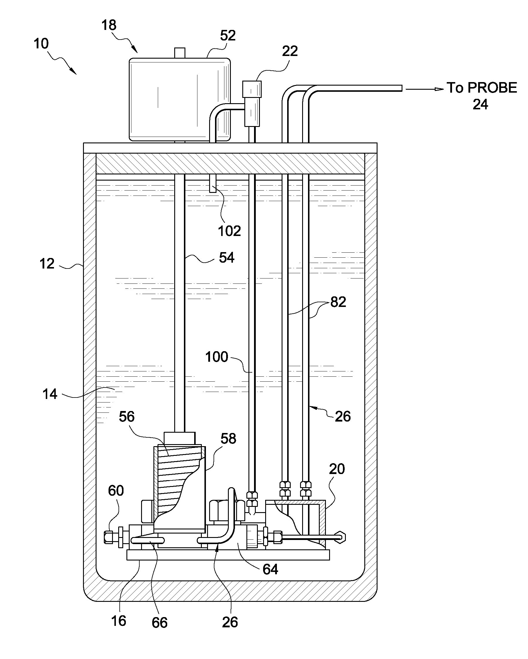
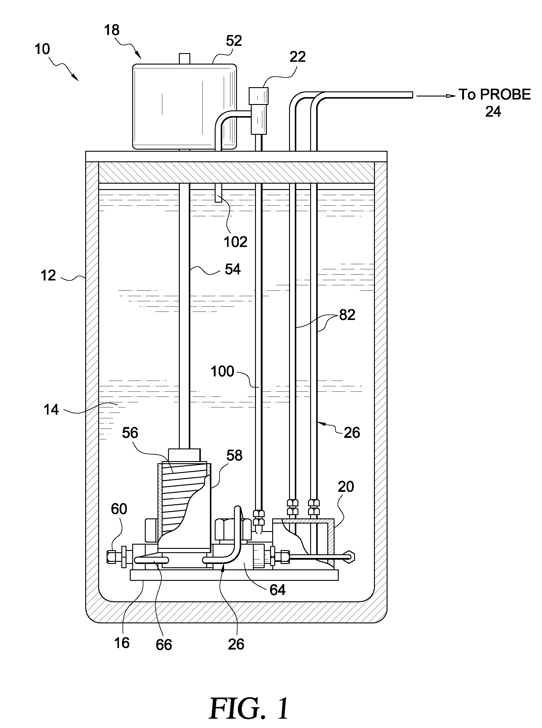
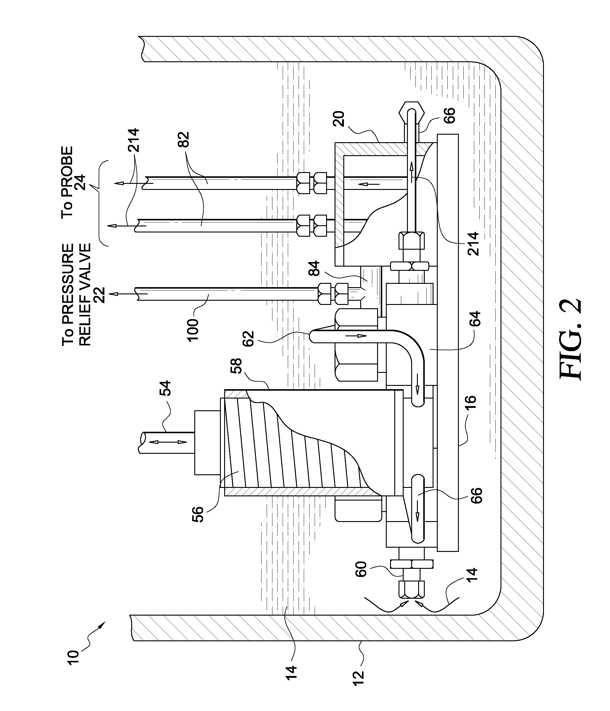
[0019]FIGS. 1-8 illustrate a preferred embodiment of a cryogenic pump, system, and method according to the present invention. The system 10 provides instantaneous sub-cooling of liquid cryogen 14, thereby creating a cryogen state characterized by an excess capacity to absorb heat without boiling. By manipulating the pressure relationships in the plumbing circuit 26, sub-cooled liquid 214 is transported to the distal cryoprobe tip 130 in 1-20 seconds allowing near instantaneous freezing at the probe tip 130. This rate of cooling is faster and the attainable low temperature is lower than comparable Joule-Thompson-based cryogenic devices.

[0020]The illustrated system 10 includes a container or dewar 12 containing cryogen 14, such as liquid nitrogen. A support 16 is positioned within the container 12 and submerged within the cryogen 14. A pump 18 is coupled to the container 12 such that the piston 56, illustrated in the form of a bellows, is also submerged within the cryogen 14. By way o...


PUM


Abstract

A cryosurgical system and method for supplying cryogen to a probe. The system including a container filled with cryogen and having bellows of a pump submerged within said cryogen. Conduits fluidly interconnect the bellows and a probe that is outside the container to permit the cryogen to be forced from the bellows to the probe upon activation of pump. A pressure relief valve is fluidly coupled to the conduits and positioned between the bellows and the probe. After initially forcing cryogen to the probe at a pressure that establishes a colligative-based sub-cooling of the liquid cryogen, the pressure relief valve is activated to lower the pressure of the cryogen to a running pressure.

Description

CROSS REFERENCE TO RELATED APPLICATIONS[0001]This is a continuation of U.S. Ser. No. 10 / 478,937 entitled Cryogenic System, filed May 14, 2004, now U.S. Pat. No. 7,192,426, which claims the benefit of PCT Application No. PCT / US02 / 17104, filed May 31, 2002, which claims the benefit of U.S. Provisional Application Ser. No. 60 / 294,256, filed on May 31, 2001. The entire contents of U.S. Ser. No. 10 / 478,937, PCT Application No. PCT / US02 / 17104 (WO 02 / 096,270), and U.S. Ser. No. 60 / 294,256 are incorporated herein by reference thereto.BACKGROUND OF THE INVENTION[0002]1. Field of the Invention[0003]The present invention relates to a cryogenic system. More specifically, illustrative embodiments of the present invention relate to a cryogenic system for use in cryosurgical procedures.[0004]2. Description of the Related Art[0005]The distribution of boiling (liquid) cryogens, such as liquid nitrogen, is problematic due to the parasitic heat load provided by a cryosurgical device's plumbing or tran...

Claims


Application Information

Patent Timeline
Patent Type & Authority Patents(United States)
IPC IPC(8): A61B18/02F17C13/00
CPCA61B18/02
Inventor BAUST, JOHN G.CHEEKS, ROY
Owner VARIAN MEDICAL SYSTEMS
Learn More