Method and system for ripple-spring compression assessment

a ripple spring and compression technology, applied in the field of dynamoelectric machines, can solve problems such as inspections, and loosening of statator wedges, and achieve the effects of avoiding failure of electric generators, and avoiding failure of dynamoelectric generators

Inactive Publication Date: 2008-09-02
SIEMENS ENERGY INC
View PDF9 Cites 12 Cited by
  • Summary
  • Abstract
  • Description
  • Claims
  • Application Information

AI Technical Summary

Problems solved by technology

Over time, stator wedges may become loose.
If a stator wedge becomes loose, it can permit a stator coil to vibrate, which can cause catastrophic failure in an electric generator.
However, such inspections present a challenge because ripple springs are difficult to access within a generator and because they are concealed by the corresponding stator wedge.
There are significant challenges associated with the conventional approaches to testing ripple-spring tightness.
Manually tapping stator wedges is also only possible after a generator's rotor has been removed from the generator.
The second approach, using a depth gauge to take measurements through pre-formed test holes, is time consuming.
This approach is also only possible when a generator has pre-formed test holes in its stator wedges.
This method is not ideal because it involves only an indirect indication of ripple-spring compression.
This approach also requires a relatively complex algorithm for converting the displacement of the stator wedge into an indication of ripple-spring compression.

Method used


Image

  • Method and system for ripple-spring compression assessment
  • Method and system for ripple-spring compression assessment
  • Method and system for ripple-spring compression assessment

Examples


Embodiment Construction

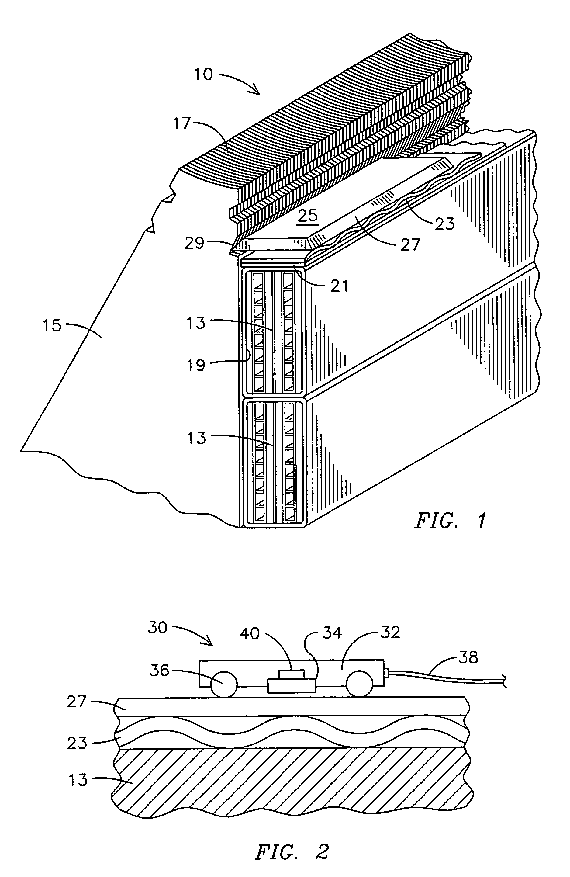
[0018]FIG. 1 illustrates an example of a stator 10 to which methods and systems of the present invention may be applied. The stator 10 includes stator teeth 15; which are formed from multiple, stacked laminations 17. The stator 10 also includes stator slots 19 in which stator coils 13 may be stacked. The stator coils 13 are retained in the slots 19 by shims 21, ripple springs 23, and stator wedges 25 having beveled edges 27 for engaging correspondingly shaped grooves 29 in the sidewalls of the stator teeth 15. The ripple springs 23 are compressed between the stator wedges 25 and shims 21 to generate a force that firmly holds the stator coils 13 in place. Over time, the ripple springs 23 may lose their resiliency so that the stator wedges 25 become loose. This can permit the stator coils 13 to vibrate, which can result in damage to the stator 10 and eventual failure of the electrical generator.

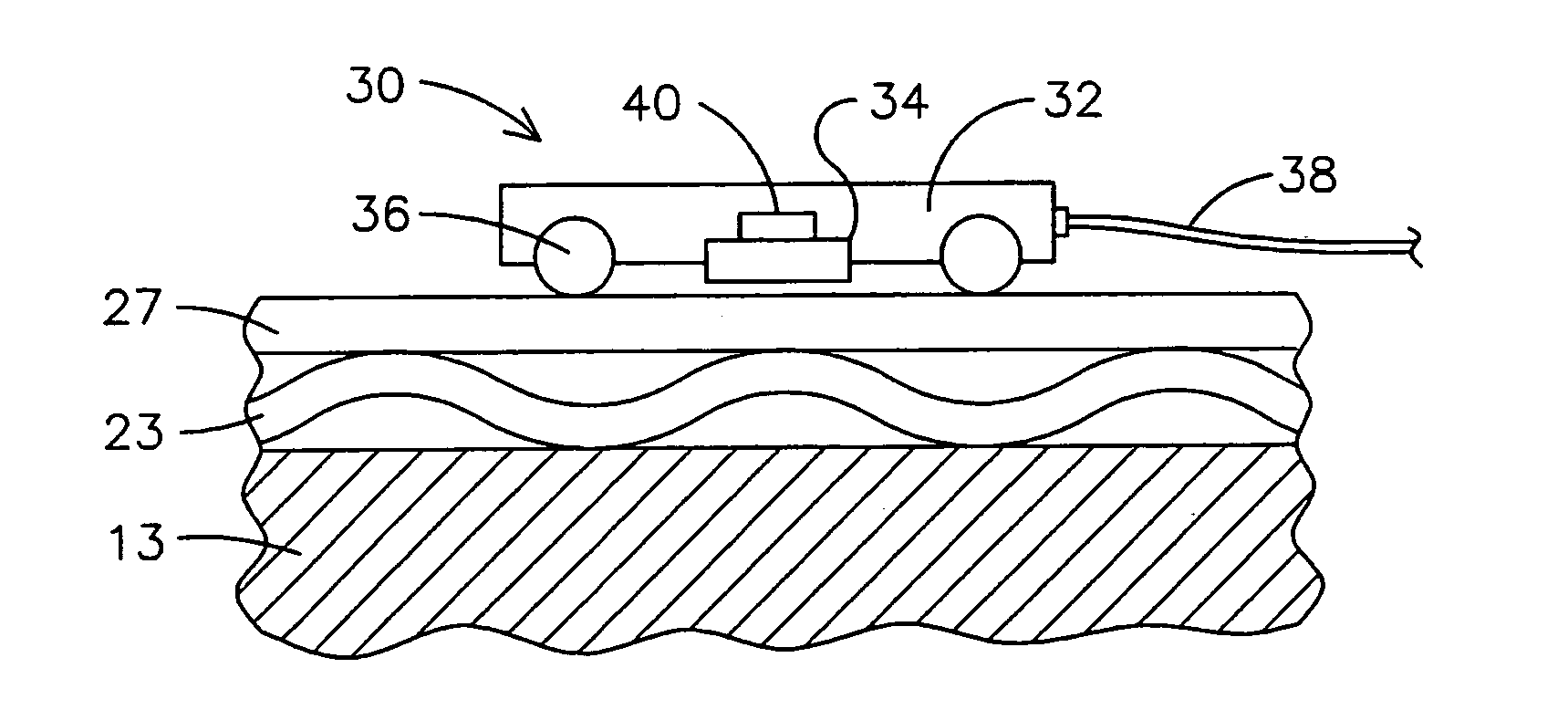
[0019]FIG. 2 illustrates a compression-assessment tool 30 for assessing the tightness of ri...


PUM

PropertyMeasurementUnit
lengthaaaaaaaaaa
forceaaaaaaaaaa
electrically woundaaaaaaaaaa

Abstract

A method and system for directly measuring the compression of a ripple spring (23) in a dynamoelectric machine through a corresponding wedge (27). A compression-assessment tool (3) is provided that includes a carriage (32) for supporting a proximity sensor (34). The carriage (32) enables the proximity sensor (34) to be passed over the length of the ripple spring (23), which produces an output signal that is representative of the compression of the ripple spring (23).

Description

FIELD OF THE INVENTION[0001]The present invention relates generally to the assessment of the condition of dynamoelectric machines, and more particularly to methods and systems for measuring the compression of ripple springs in dynamoelectric machines. Although the following discussion focuses on electric generators, methods and systems consistent with the present invention are applicable to other dynamoelectric machines, including electric motors.BACKGROUND[0002]Electric generators include a rotor and a stator. Rotors are generally constructed from a steal forging and include a number of slots that run the length of the rotor. Rotors are electrically wound by placing conductors referred to as rotor windings into the slots of the rotor.[0003]Stators are generally constructed from a number of stacked, metal laminations. Stators also include slots, which run the length of the stator. Stators are electrically wound by placing conductors known as stator coils into the slots of the stator...

Claims


Application Information

Patent Timeline
Patent Type & Authority Patents(United States)
IPC IPC(8): G01L1/04
CPCH02K15/00G01N2203/0288H02K15/0018H02K3/487
Inventor FISCHER, MARK WILLIAMDIEBACKER, HANSSILL, HARRY L.ARBOGAST, PHILIP M.
Owner SIEMENS ENERGY INC
Why Eureka
Try Eureka