
Integrated mount duct for use with airborne auxiliary power units and other turbomachines

a technology of auxiliary power units and integrated mounts, which is applied in the direction of machine supports, efficient propulsion technologies, machines/engines, etc., can solve the problems of not being compatible with the standard mounting components of the mounting system is disclosed, and the new equipment cannot utilize the standard mounting hardware and associated components described abov

Inactive Publication Date: 2008-09-02
HONEYWELL INT INC
View PDF36 Cites 17 Cited by
  • Summary
  • Abstract
  • Description
  • Claims
  • Application Information

AI Technical Summary

Problems solved by technology

Such new equipment cannot utilize the standard mounting hardware and associated components described above, even though it remains economically feasible to continue using these components, even for new designs, and specialized mounting methods are used.
The mounting system disclosed by Cornax '223 is thus not compatible with standard mounting components.

Method used


Image

  • Integrated mount duct for use with airborne auxiliary power units and other turbomachines
  • Integrated mount duct for use with airborne auxiliary power units and other turbomachines
  • Integrated mount duct for use with airborne auxiliary power units and other turbomachines

Examples


Embodiment Construction

[0034]The following detailed description is of the best currently contemplated modes of carrying out the invention. The description is not to be taken in a limiting sense, but is made merely for the purpose of illustrating the general principles of the invention, since the scope of the invention is best defined by the appended claims.

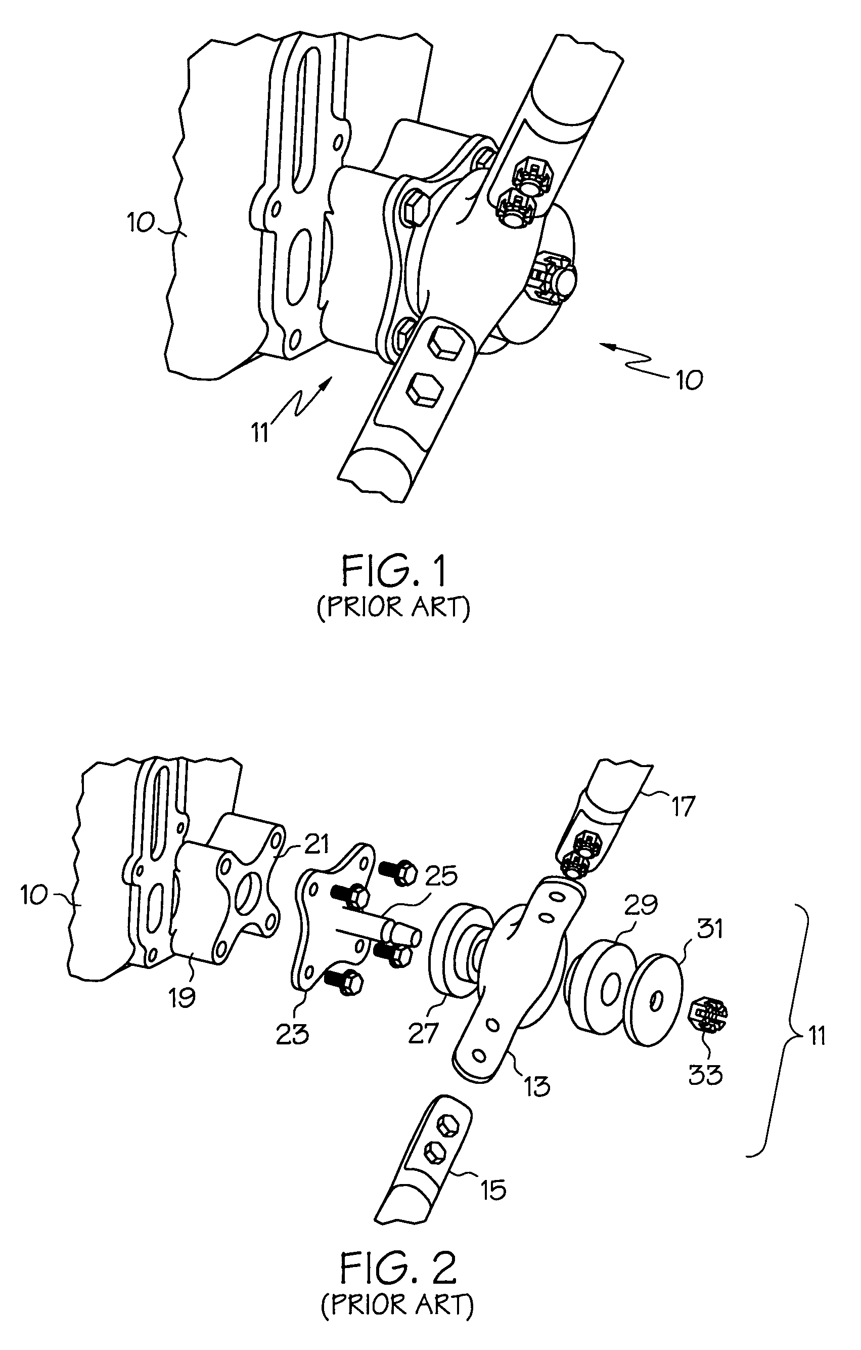
[0035]Broadly, the present invention generally provides an apparatus and method for utilizing conventional cloverleaf strut mounting components with new airborne turbomachinery for mounting such new turbomachinery on a flight vehicle. In the present state of the art, the design specifications of new airborne turbomachinery preclude the use of such conventional cloverleaf strut mounting components.

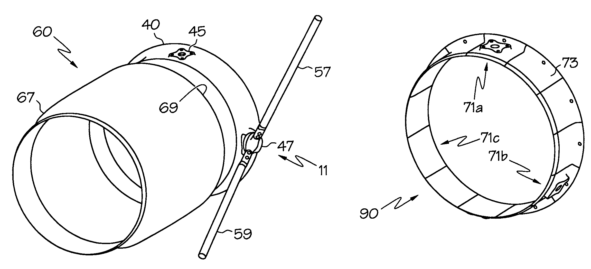
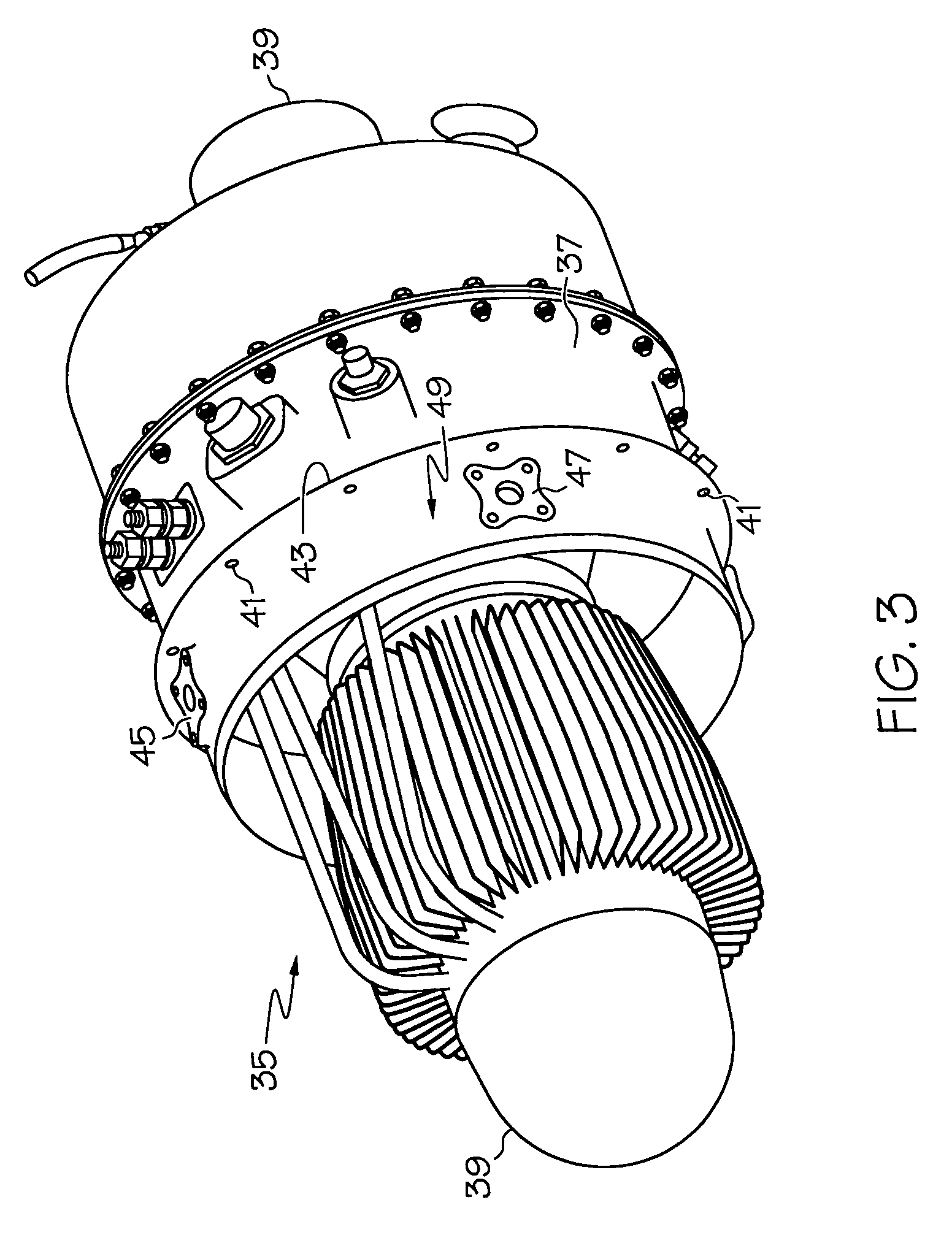
[0036]In the present invention, a cylindrical load ring having a mount flange edge and having one or more mechanical attachment members, such as load ring pads, adapted for mounting components is attached at the mount flange edge to an enclosure component in th...


PUM


Abstract

An integrated mount duct includes a load ring for mounting a turbomachine to a flight vehicle, wherein the load ring has a cylindrical shape with a flange edge and a stepped edge, and comprises one or more mechanical attachment members disposed on an outside surface of the load ring, the mechanical attachment members configured to mate with a strut.

Description

BACKGROUND OF THE INVENTION[0001]The present invention generally relates to airborne ancillary turbomachinery, and in particular to a method and device for mounting such equipment to flight vehicle structures.[0002]A typical flight vehicle, such as an aircraft, may include a turbomachine such as an Auxiliary Power Unit (APU) 10, partially shown in FIG. 1, used to provide electrical and pneumatic power to various parts of the aircraft (not shown) for environmental control, interior lighting, electronic power, and starting a main engine.[0003]The conventional APU 10 may be mounted to the aircraft by means of struts or links attached to an APU gearbox pad 19. As shown in FIG. 2, a standard cloverleaf strut mounting assembly 11 (here shown in an exploded view) may include a finger mount 13, a stud adapter 23, a first vibration isolator 27, and a second vibration isolator 29. The stud adapter 23 may be removably attached to the conventional APU 10, typically by using mechanical fasteners...

Claims


Application Information

Patent Timeline
Patent Type & Authority Patents(United States)
IPC IPC(8): B64D27/00F02C6/00F16L3/08
CPCB64D41/00F02C7/20F01D25/243B64D2041/002Y02T50/671Y02T50/44Y02T50/40Y02T50/60Y10T137/0536
Inventor WILLIAMS, NICHOLAS A.
Owner HONEYWELL INT INC
Learn More