

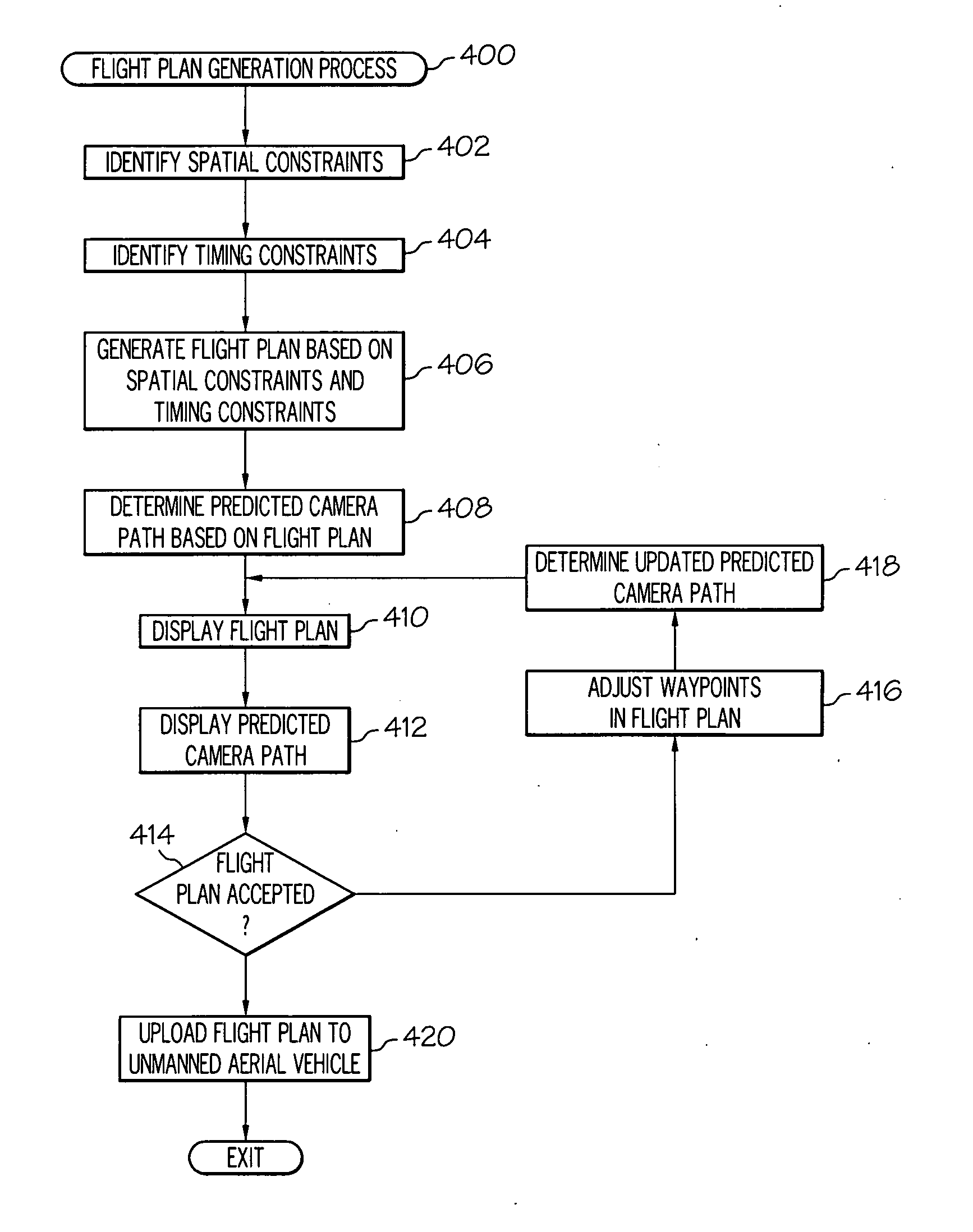
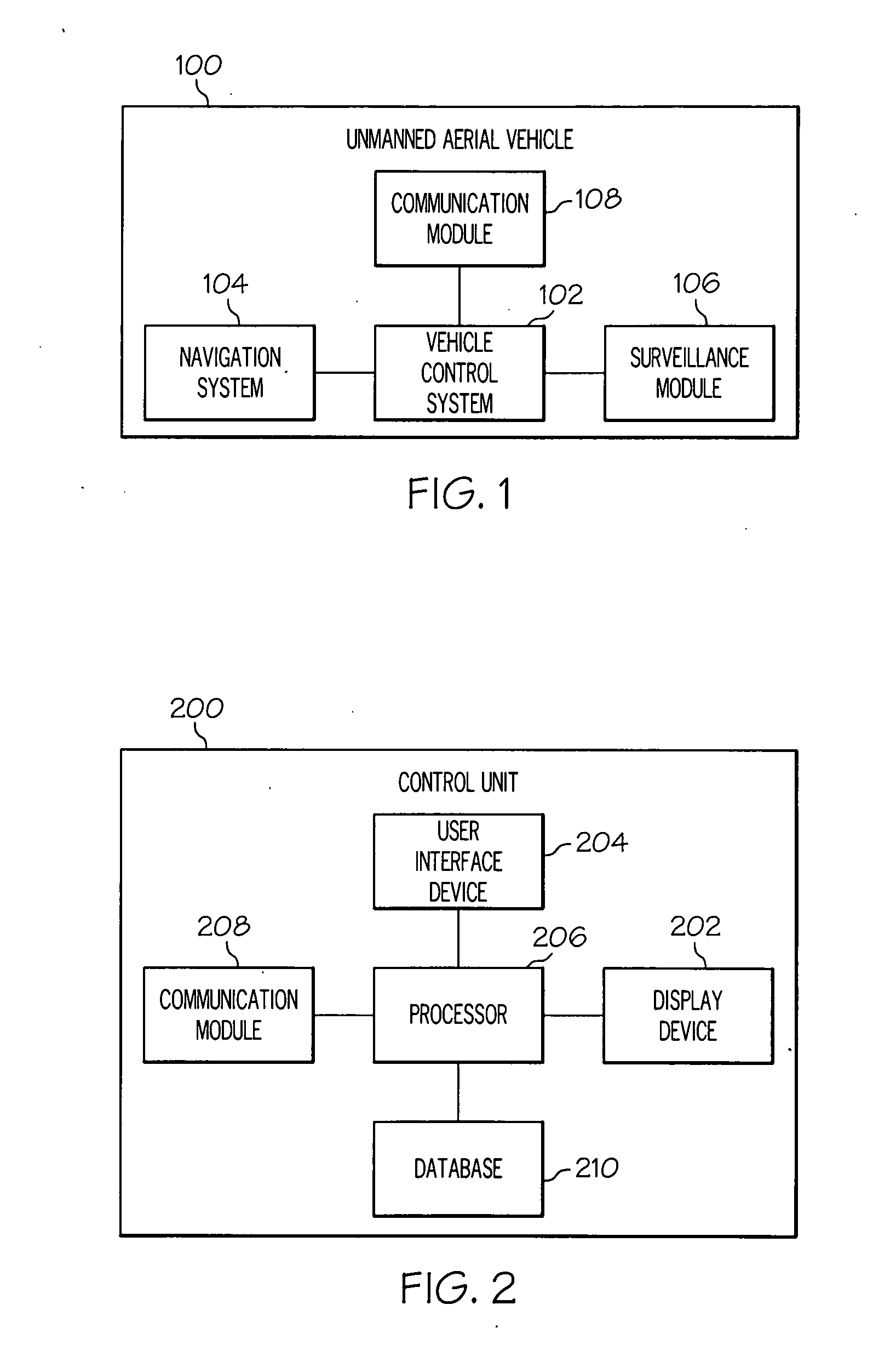
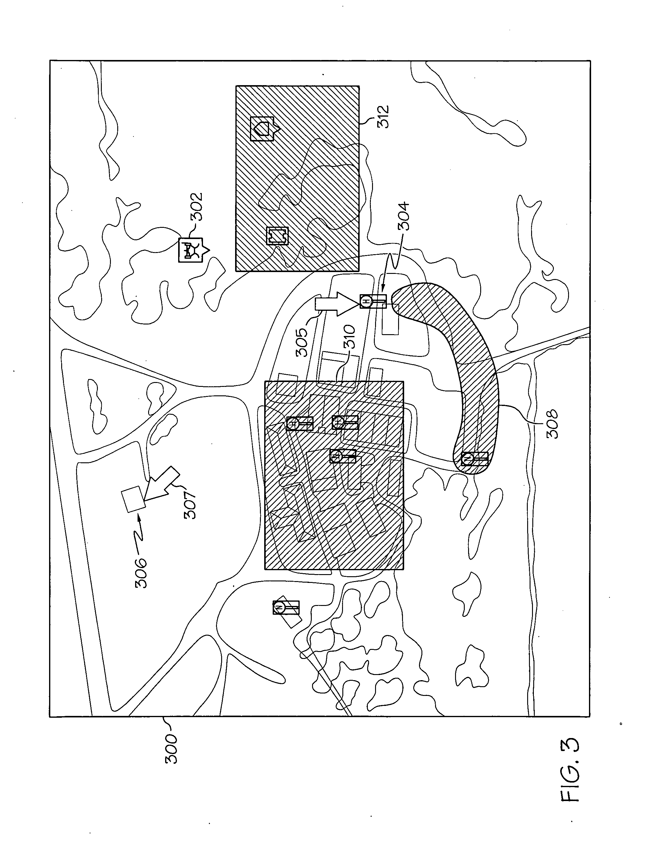
Methods for generating a flight plan for an unmanned aerial vehicle based on a predicted camera path
- Summary
- Abstract
- Description
- Claims
- Application Information
AI Technical Summary
Benefits of technology
Problems solved by technology
Method used
Image

Examples
Embodiment Construction
[0013]The following detailed description is merely exemplary in nature and is not intended to limit the subject matter of the application and uses thereof Furthermore, there is no intention to be bound by any theory presented in the preceding background or the following detailed description.
[0014]Techniques and technologies may be described herein in terms of functional and / or logical block components, and with reference to symbolic representations of operations, processing tasks, and functions that may be performed by various computing components or devices. It should be appreciated that the various block components shown in the figures may be realized by any number of hardware, software, and / or firmware components configured to perform the specified functions. For example, an embodiment of a system or a component may employ various integrated circuit components, e.g., memory elements, digital signal processing elements, logic elements, look-up tables, or the like, which may carry ...
PUM
 Abstract
Description
Claims
Application Information