Controlled take-off and flight system using thrust differentials

a thrust differential and control technology, applied in the direction of vertical landing/take-off aircraft, aircraft navigation control, transportation and packaging, etc., can solve the problems of inability to always have a runway and impracticality of us

Inactive Publication Date: 2011-02-24
TRANSITION ROBOTICS INC
View PDF29 Cites 168 Cited by
  • Summary
  • Abstract
  • Description
  • Claims
  • Application Information

AI Technical Summary

Benefits of technology

[0009]A manned/unmanned aerial vehicle adapted for vertical takeoff and landing using the same set of engines for takeoff and landing as well as for forward flight. An aerial vehicle which is adapted to takeoff with the wings in a vertical as opposed to horizontal flight attitude which takes off in this vertical attitude and then transitions to a horizontal flight path. An aerial vehicle which controls the attitude of the vehicle...

Problems solved by technology

Runways may not always be avail...

Method used


Image

  • Controlled take-off and flight system using thrust differentials
  • Controlled take-off and flight system using thrust differentials
  • Controlled take-off and flight system using thrust differentials

Examples


Embodiment Construction

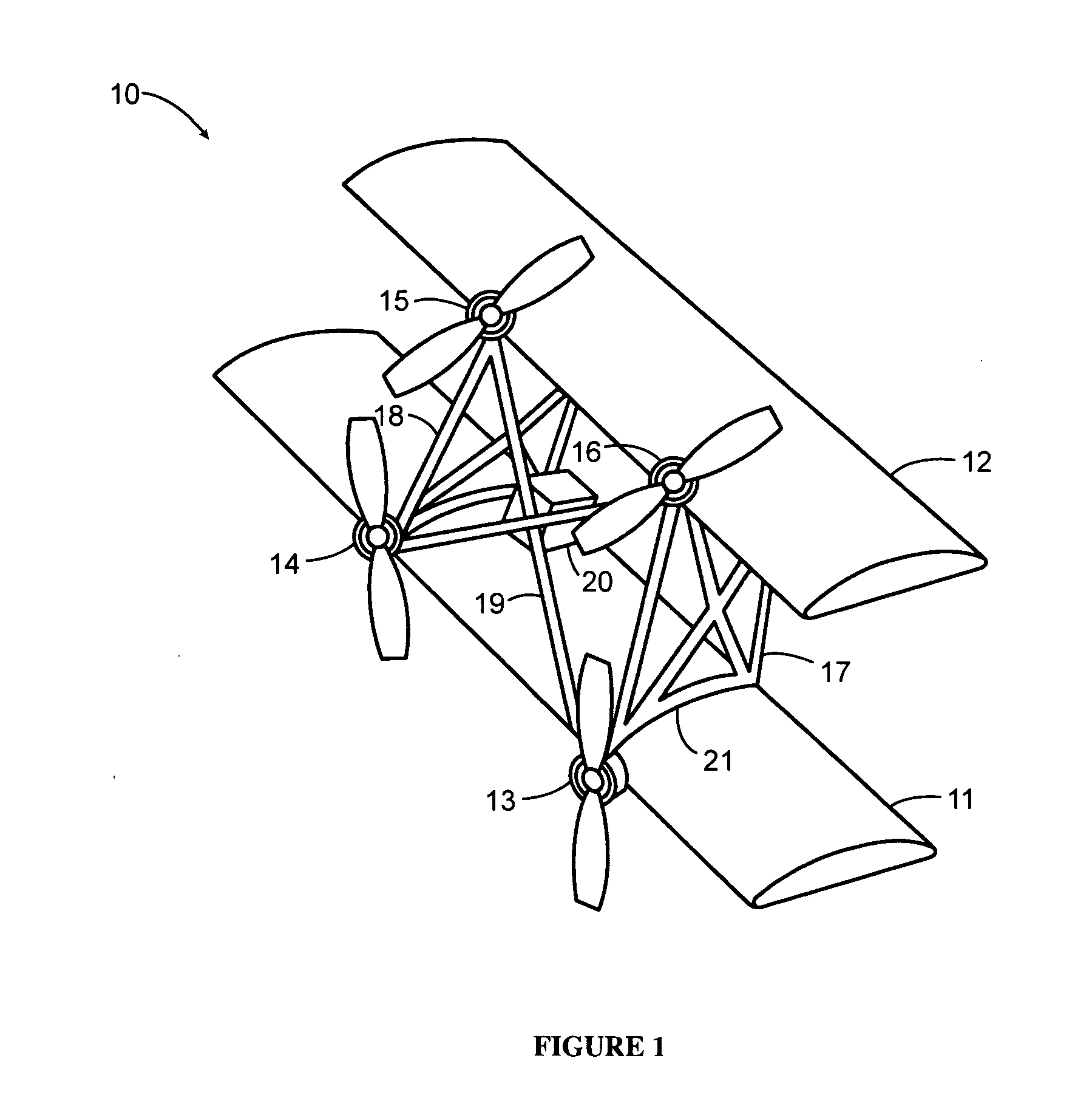
[0020]In some embodiments of the present invention, as seen in FIG. 1, an aerial vehicle 10 is seen with a first wing 11 and a second wing 12 stacked together in a biplane formation. Two thrust producing elements 13, 14 are mounted along the first wing 11, and two thrust producing elements 15, 16 are mounted along the second wing 12. A frame structure 21 is used to support loading and to position the wings 11, 12 relative to each other. The frame structure may consist of a combination of vertical elements 17, 18 and cross elements 19. The thrust producing elements 13, 14, 15, 16 are fixedly mounted to the wings 11, 12. The thrust producing elements 13, 14, 15, 16 may be electric motors with propellers in some embodiments.

[0021]In some embodiments, an electronics package 20 may be mounted within the frame structure. The electronics package may include control electronics for the aerial vehicle which may further include attitude sensors as well as motor control electronics. In some em...


PUM


Abstract

A manned/unmanned aerial vehicle adapted for vertical takeoff and landing using the same set of engines for takeoff and landing as well as for forward flight. An aerial vehicle which is adapted to takeoff with the wings in a vertical as opposed to horizontal flight attitude which takes off in this vertical attitude and then transitions to a horizontal flight path. An aerial vehicle which controls the attitude of the vehicle during takeoff and landing by alternating the thrust of engines, which are separated in least two dimensions relative to the horizontal during takeoff. An aerial vehicle which uses a rotating platform of engines in fixed relationship to each other and which rotates relative to the wings of the vehicle for takeoff and landing.

Description

CROSS-REFERENCE TO RELATED APPLICATIONS[0001]This application claims priority to U.S. Provisional Patent Application No. 61 / 236,520, to Bevirt, filed Aug. 24, 2009.BACKGROUND[0002]1. Field of the Invention[0003]This invention relates to powered flight, and more specifically to a take-off and flight control method using thrust differentials.[0004]2. Description of Related Art[0005]There are generally three types of vertical takeoff and landing (VTOL) configurations: wing type configurations having a fuselage with rotatable wings and engines or fixed wings with vectored thrust engines for vertical and horizontal translational flight; helicopter type configuration having a fuselage with a rotor mounted above which provides lift and thrust; and ducted type configurations having a fuselage with a ducted rotor system which provides translational flight as well as vertical takeoff and landing capabilities.[0006]VTOL capability may be sought after in manned vehicle applications, such as oth...

Claims


Application Information

Patent Timeline
IPC IPC(8): B64C29/00B64C15/00
CPCB64C15/00B64C29/0025B64C2201/165B64C2201/021B64C2201/088B64C39/024B64U10/25B64U70/80B64U50/13B64U30/20B64U50/19B64U10/13B64U10/00B64C29/02
Inventor BEVIRT, JOEBEN
Owner TRANSITION ROBOTICS INC
Why Eureka
Try Eureka